Our Do It Yourself Solar Array
Jump to Decisions, Opinions, and Stories
 |
|---|
|
A word about my sponsor: |
Disclaimer: This information has been put here in the hope that someone finds it useful, We do not claim to be experts at installing a solar array, nor do we claim that the information you find here is the “best way”. The information that follows is simply how we installed a functioning 10.8 kilowatt array, that is tied to the electric grid and Co-Generates electricity with Polk Burnett Electric Cooperative. I also want to point out that working with various power tools, and working with electricity is hazardous. You need to decide for yourself if you want to do these things. Also here in Wisconsin we can still legally do our own construction and wiring. In your location that might not be true, so please check with you local building codes, if you are considering a project like this.
|
I will be leaving all the previous data. All future data will no longer be updated as Dean passed away.
Data from past months,
Jan. 2019 solar performance (PDF) Jan. 2019 Impact on our Electric purchase (PDF)
2.66 Peak KW hrs per day
Spreadsheet in Open Office format.
solar_array_bom.xls
|
|
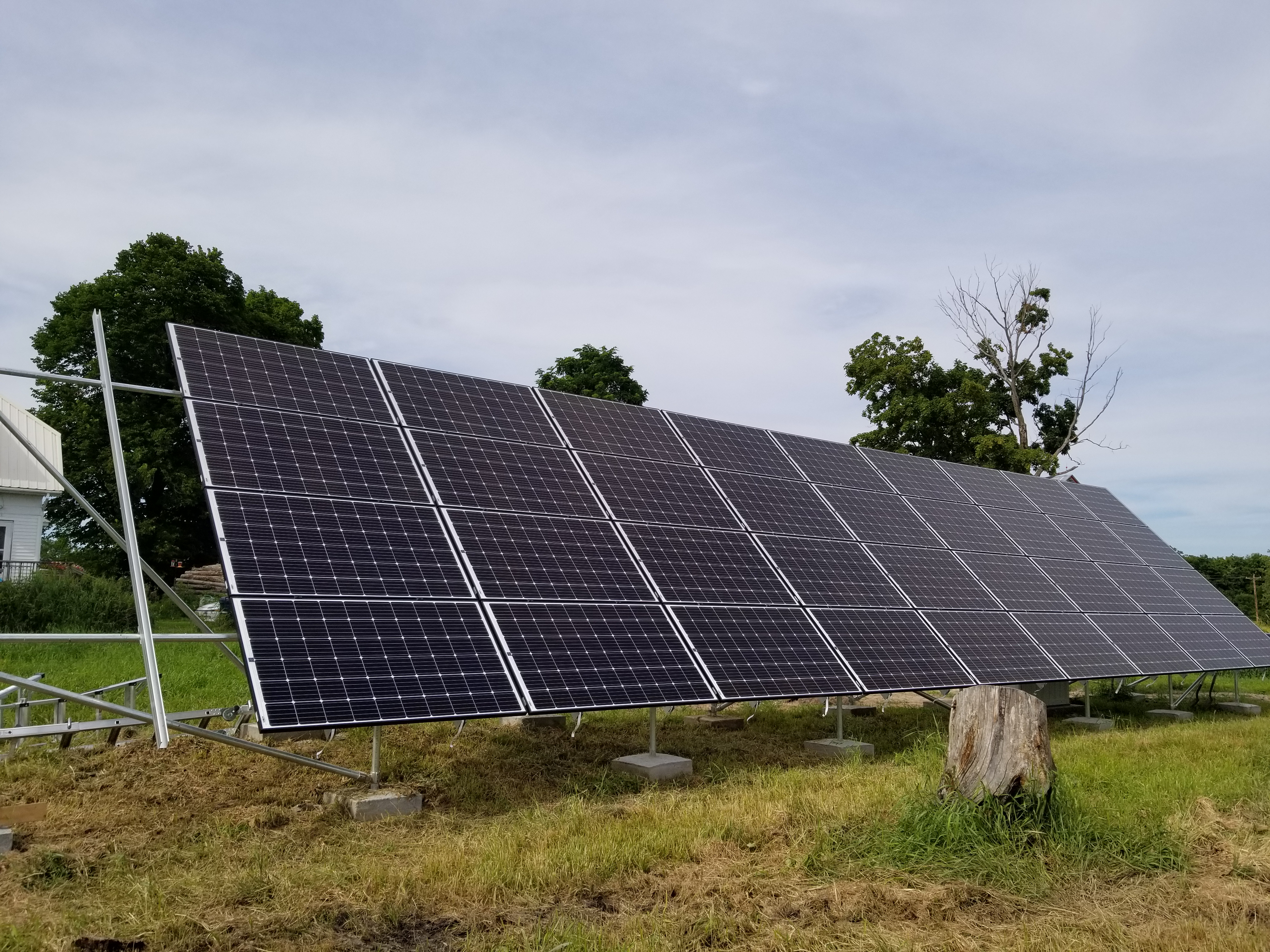
This information details the installation of a ground mounted solar array with a transformerless single phase grid tie inverter that is wired into our main electrical power source which can power our home, as well as feed power to the electric grid via a special smart meter that Polk Burnett Electric installed. |
|
|
|
|
|
|
|
|
We have some technical stuff to still work out.
|

|
Time to do the paper work! | 
|
|
|
TIMEOUT! I don’t want to deal with all this mumbo jumbo…
We chose to do it all because we figured, why not try? What do we have to lose? |

|
Approved! |

|
|
|
What we are going to put them on?
SnapNrack System 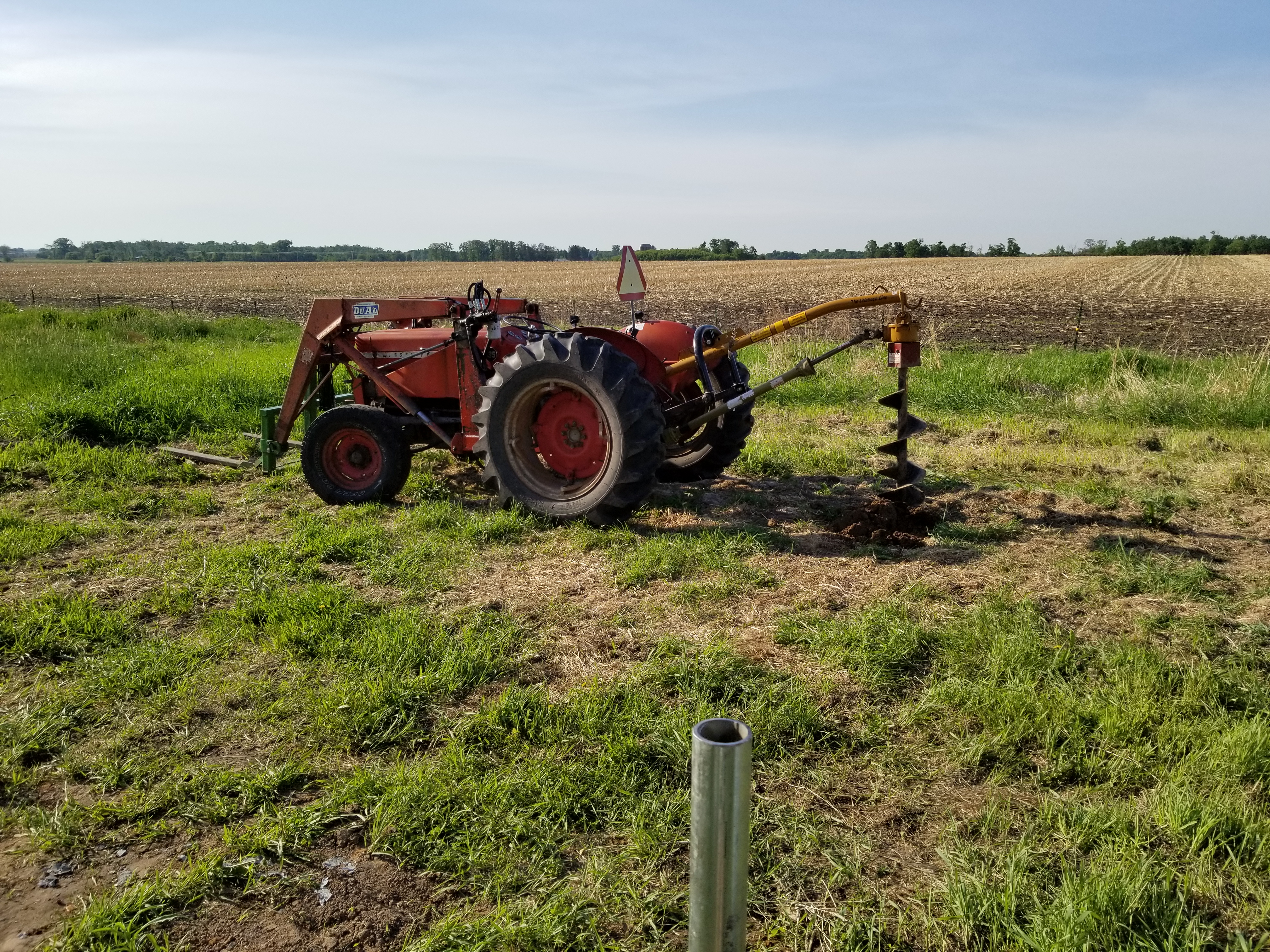
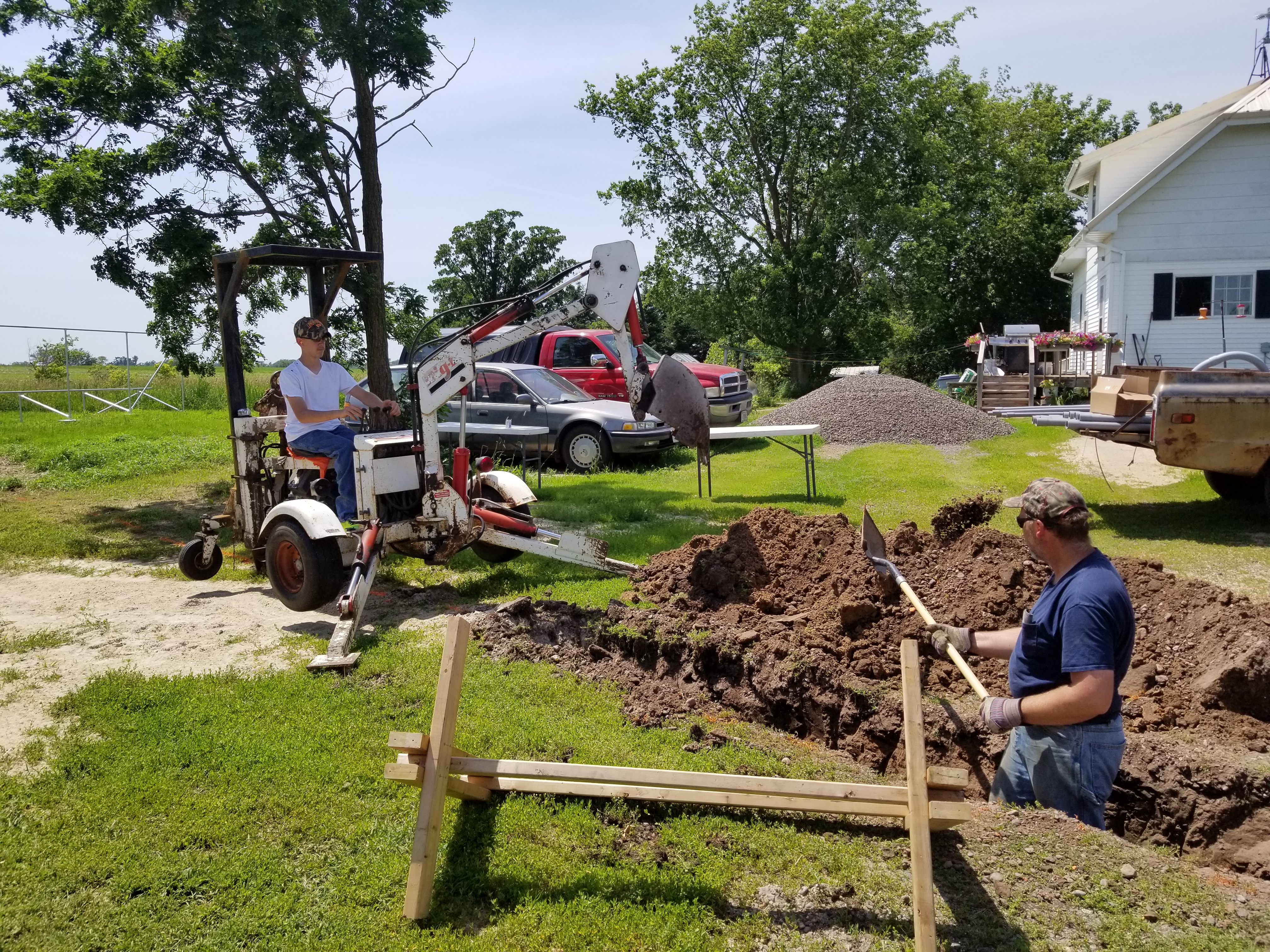
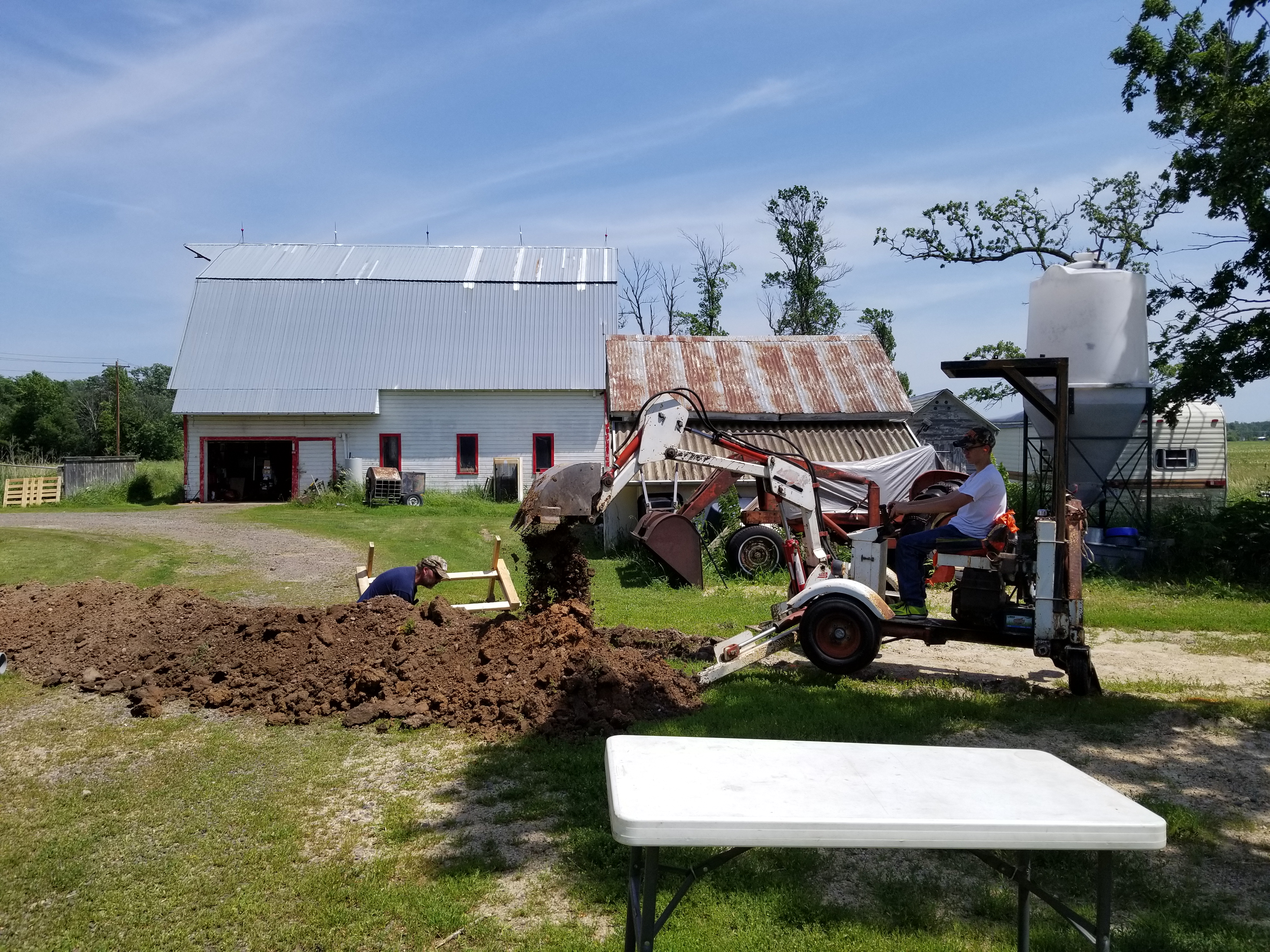
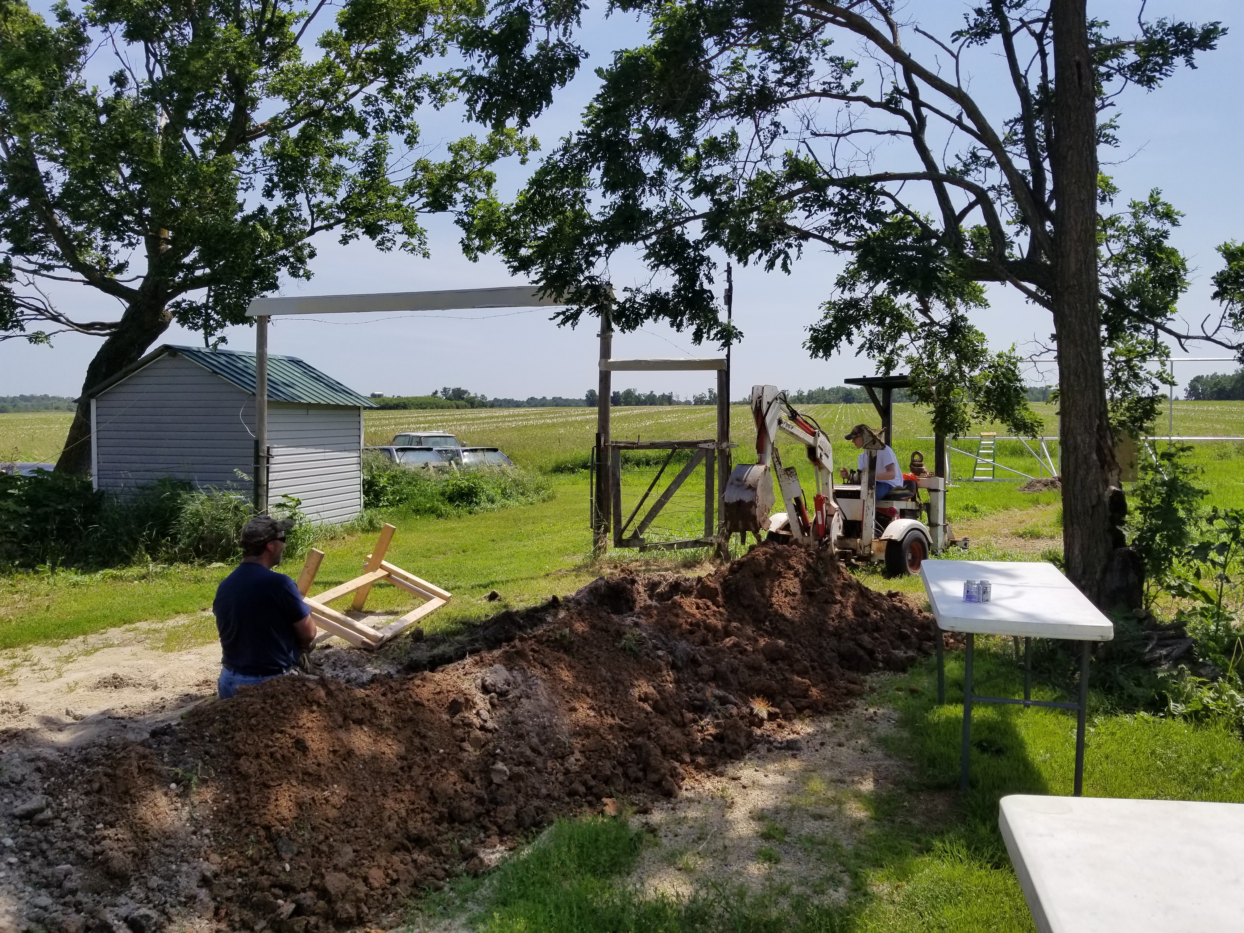
Got Auger? 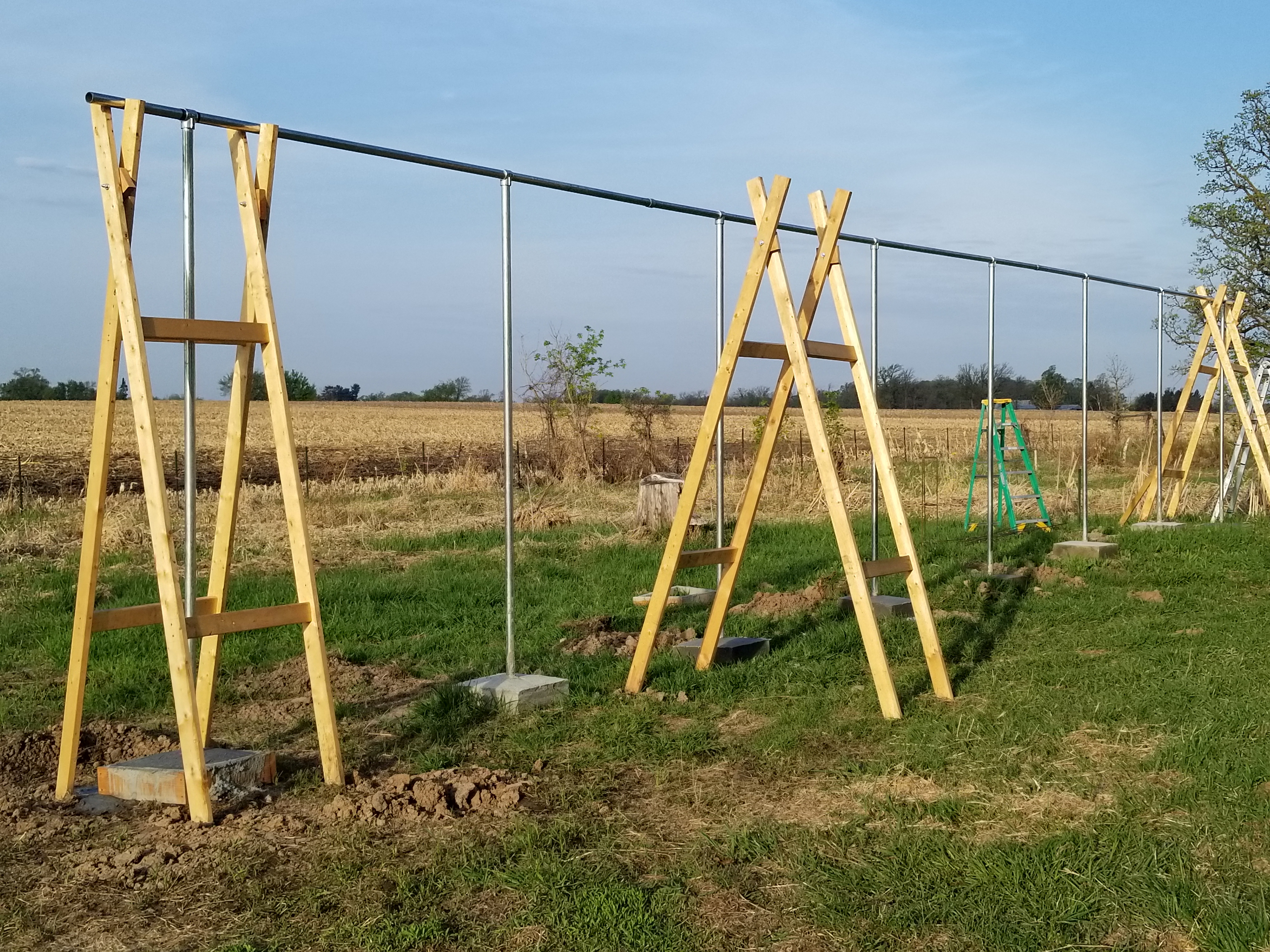
Got Wood? |
|
|
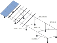
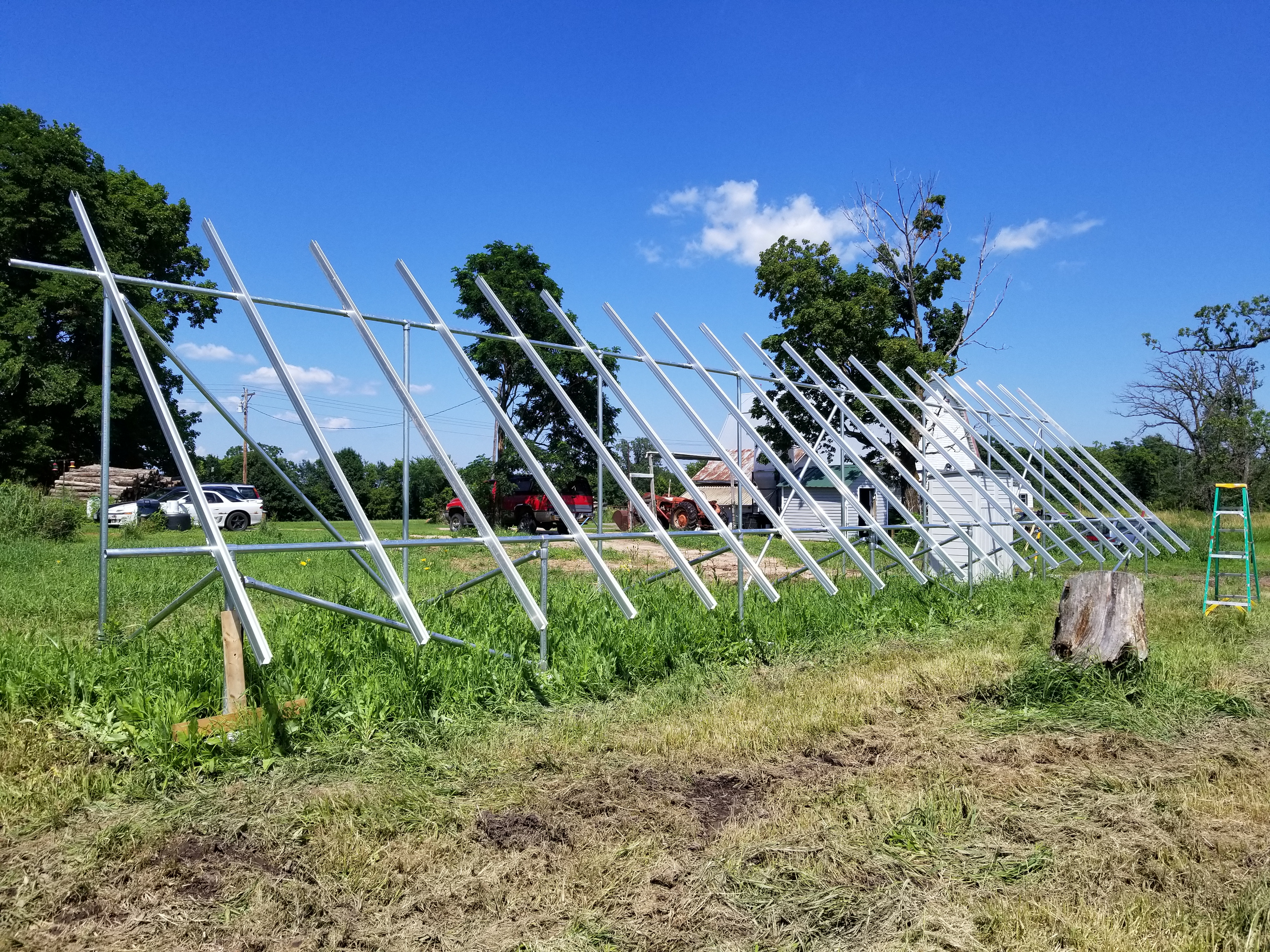
I started by making some crude CAD drawings, to get some idea of how the system would be laid out, and what the angle measurements should be.
Anyone with some basic knowledge of geometry could probably whip these numbers out with a calculator. Anyway, armed with some layout measurements, and a tape measure, my wife and I went out and put some stakes in the ground just as soon as the ground was soft enough to drive a stake into.
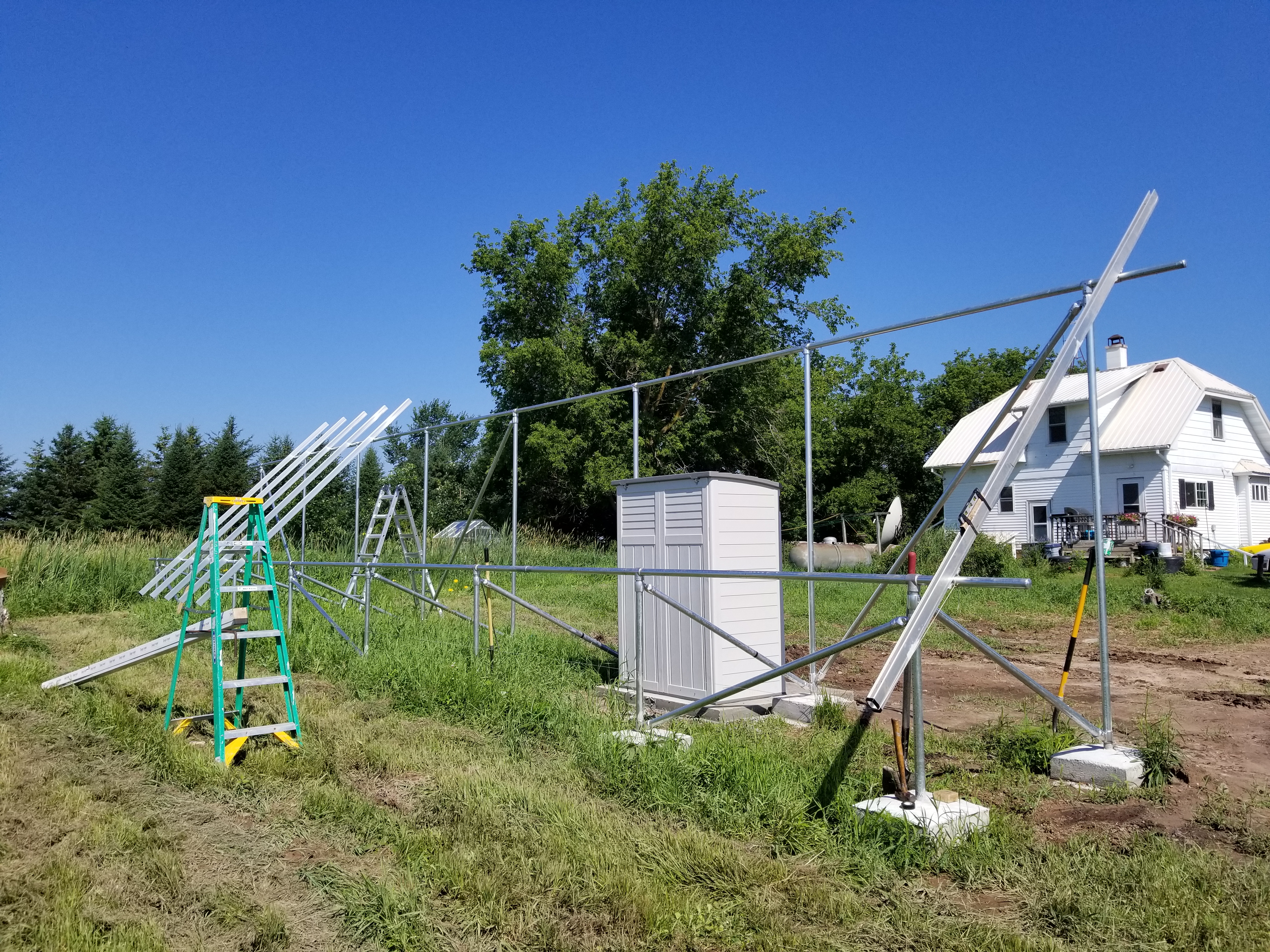
We used one of the 21ft pipes for the Horizontal run to suspend the vertical piers with the SnapNrack "tee" fittings, and the "X" support frame. 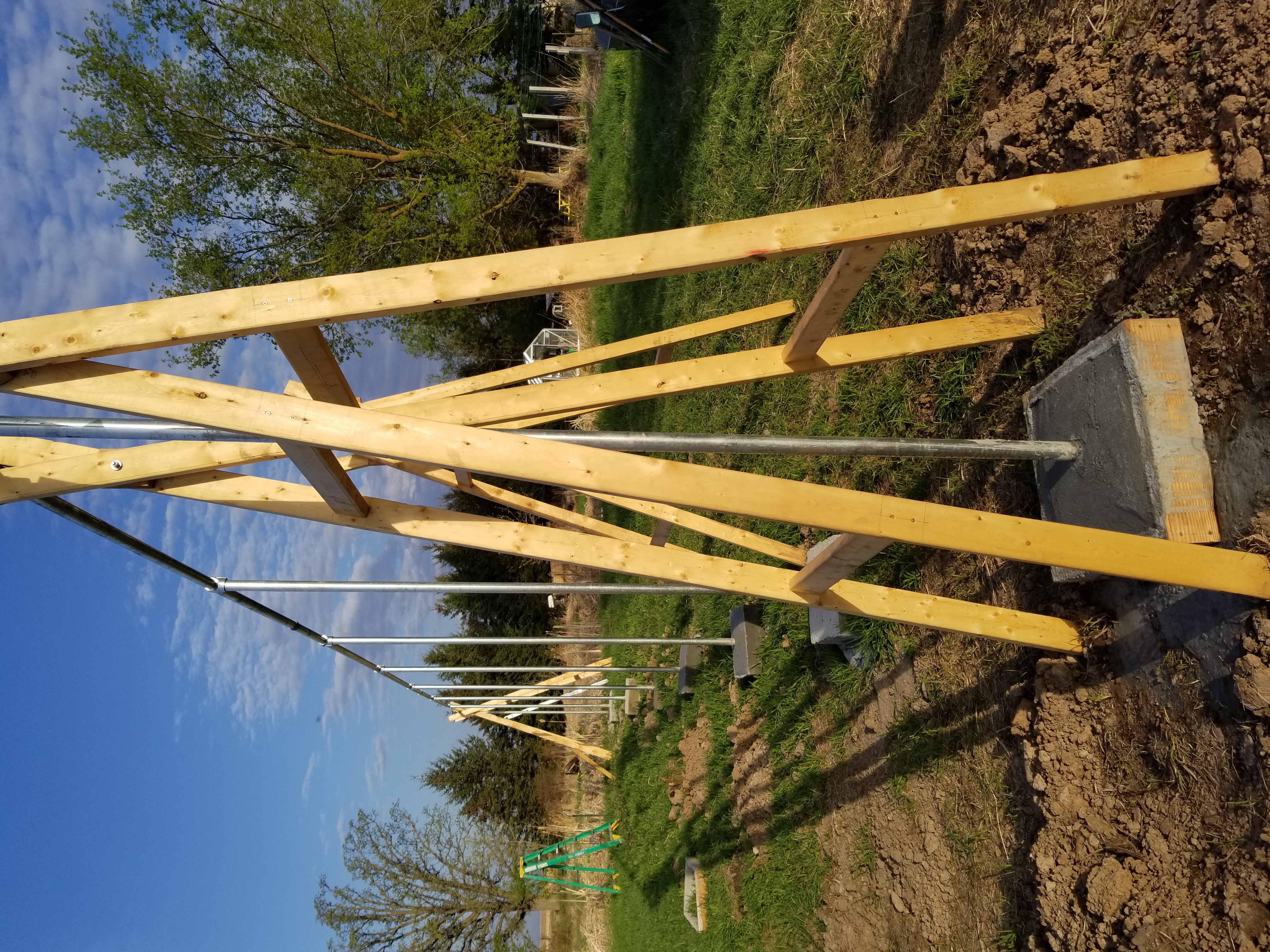
|
|
Installing the ground mount system.
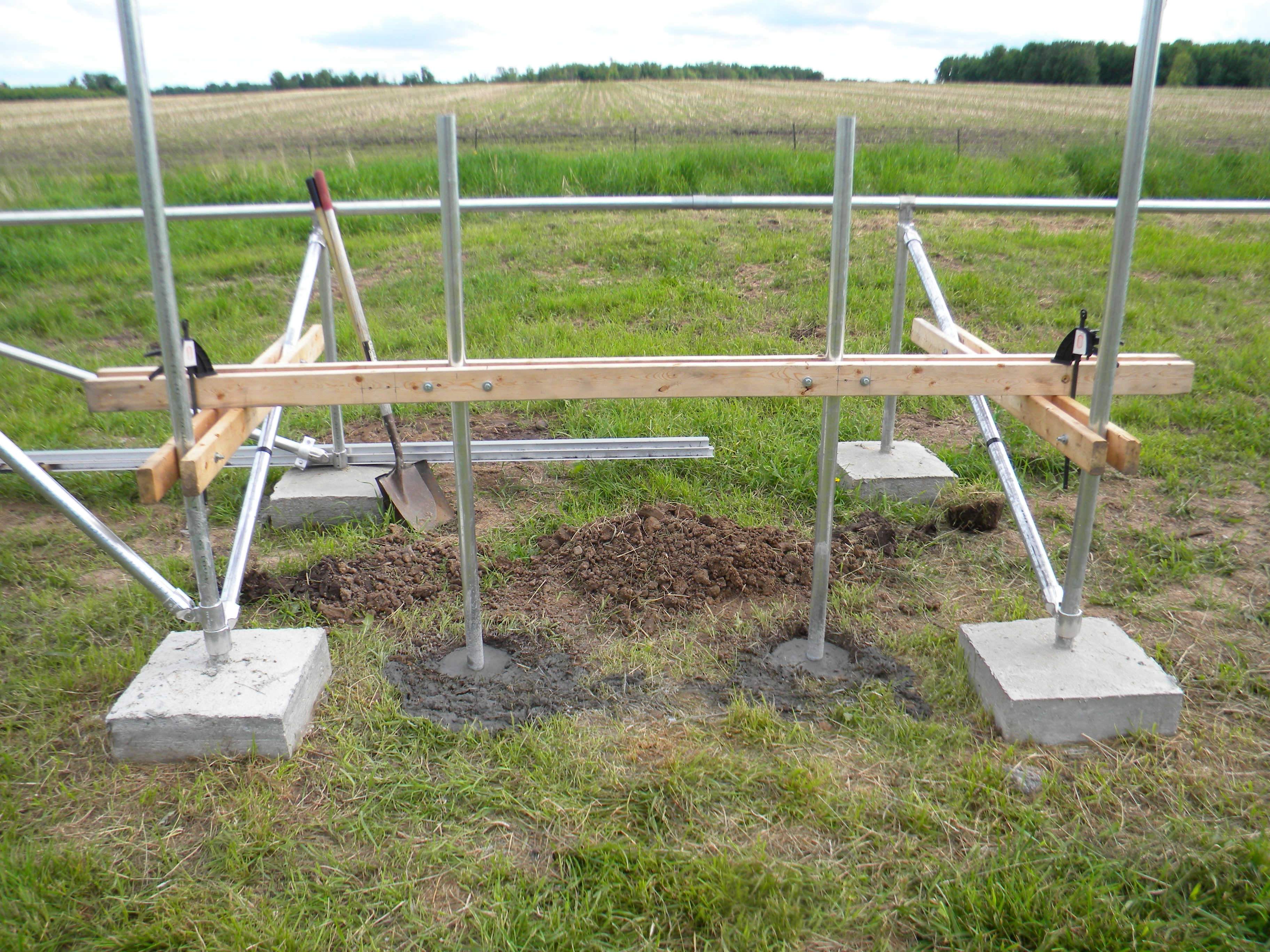
Finishing up the ends of the back piers.
|
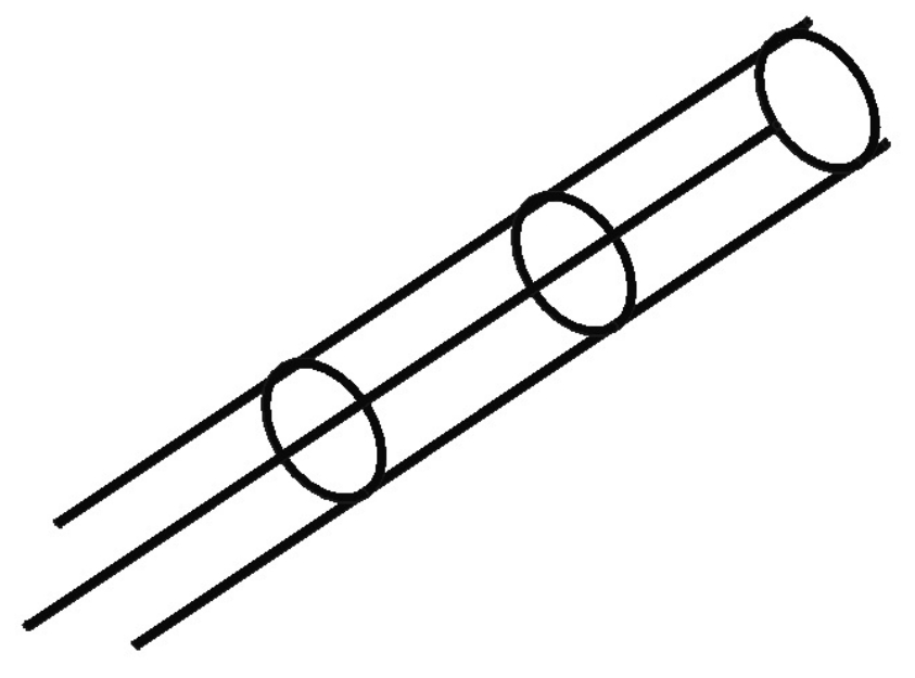
Steel re-rod assembly used in each pier base. 48" tall with 3, 6" rings welded at 18" apart.
|
NOTE: The picture below actually shows the re-rod assembly in one of the front pier holes.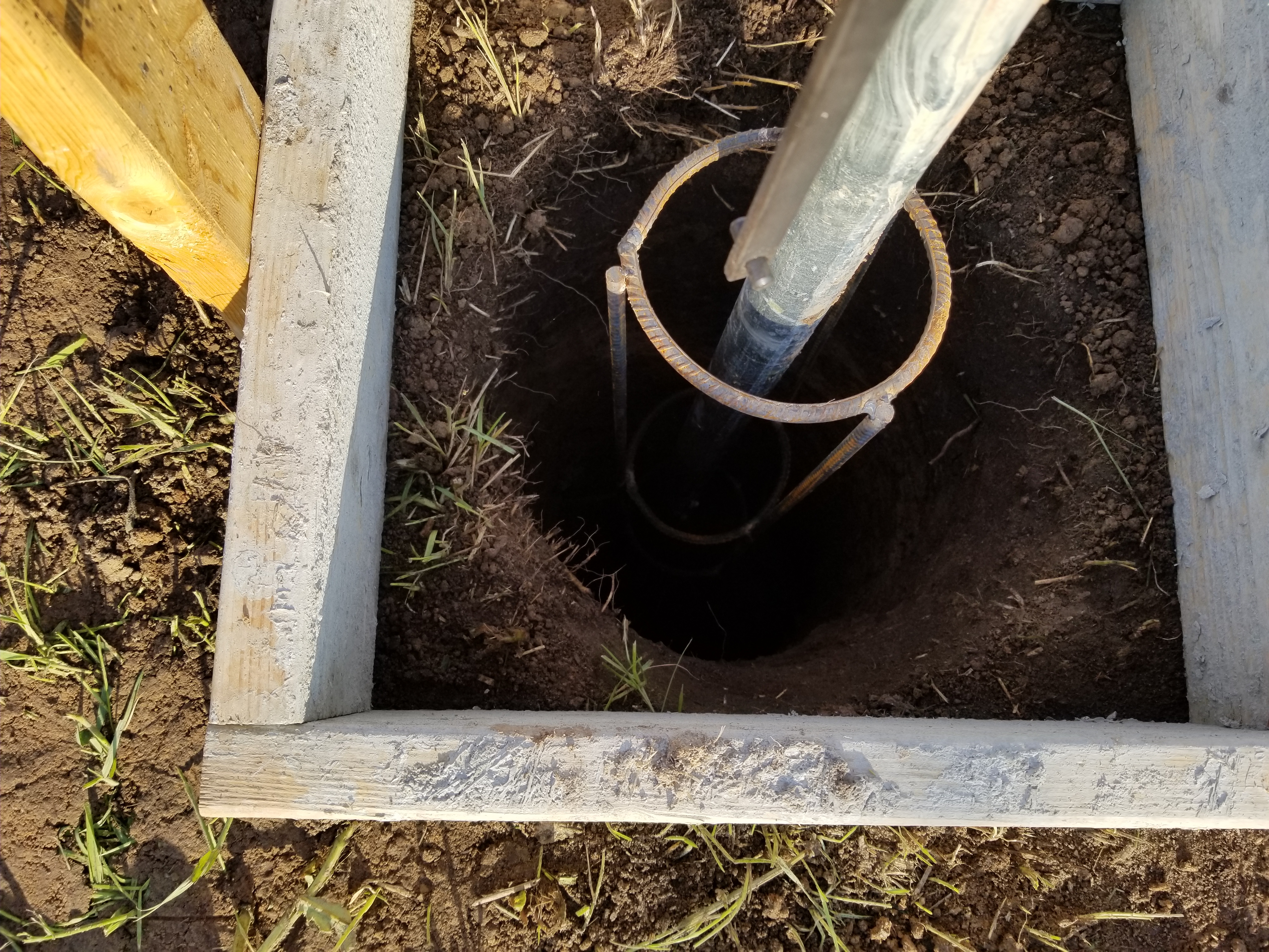
|
|
|
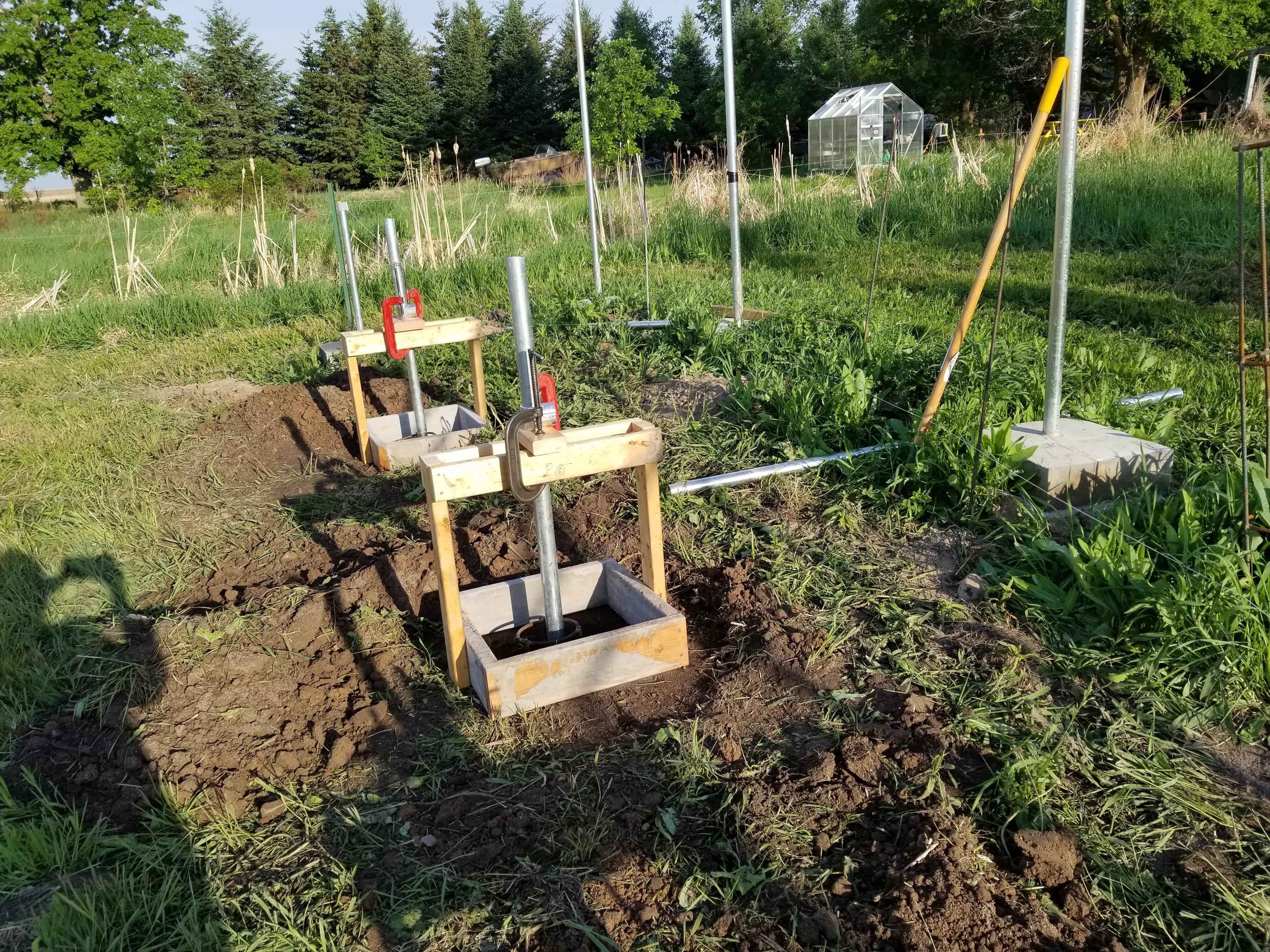
Suspended vertical piers ready for cement.
|
Vertical pier with re-rod suspended in drilled hole.
|
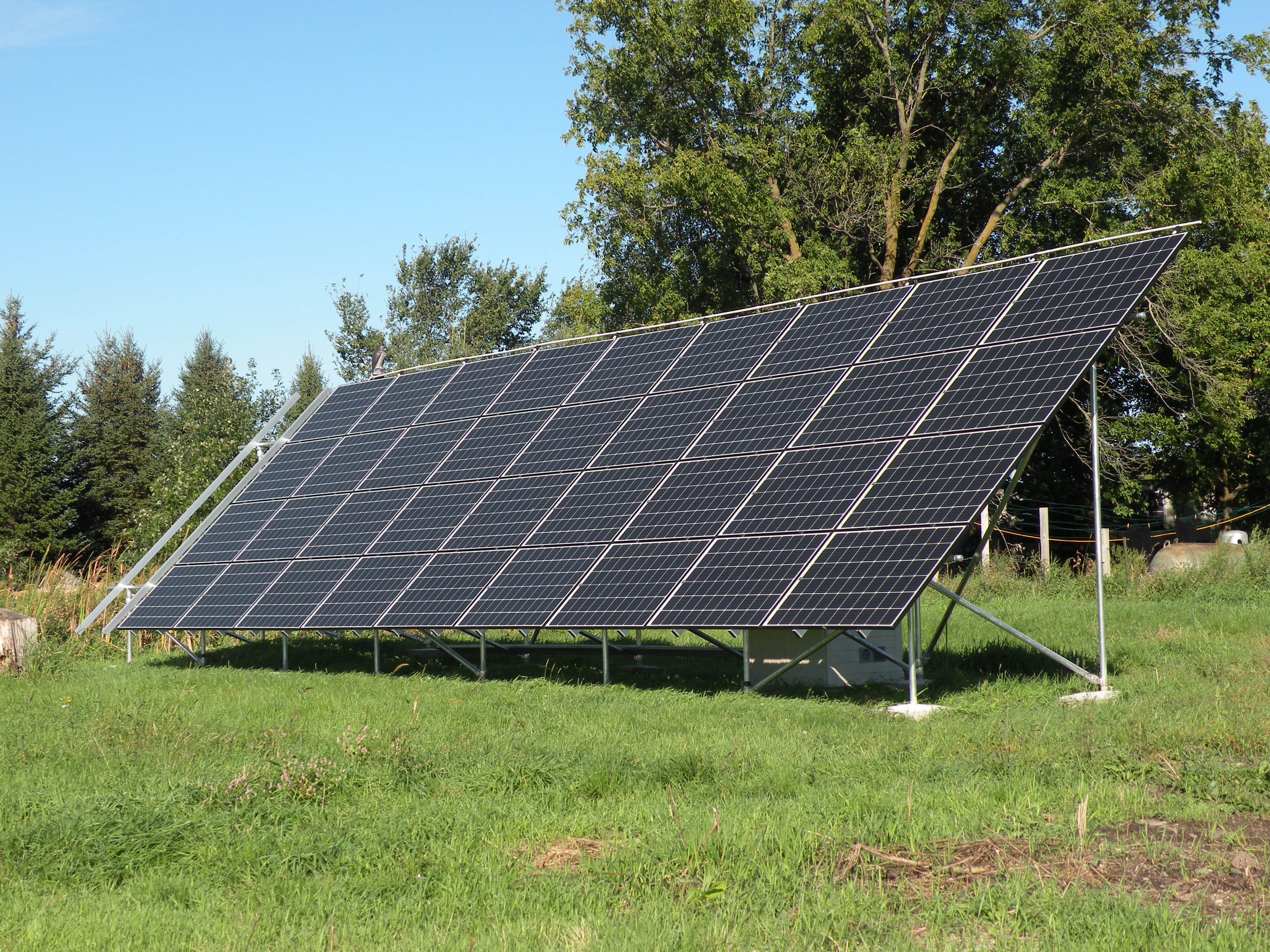
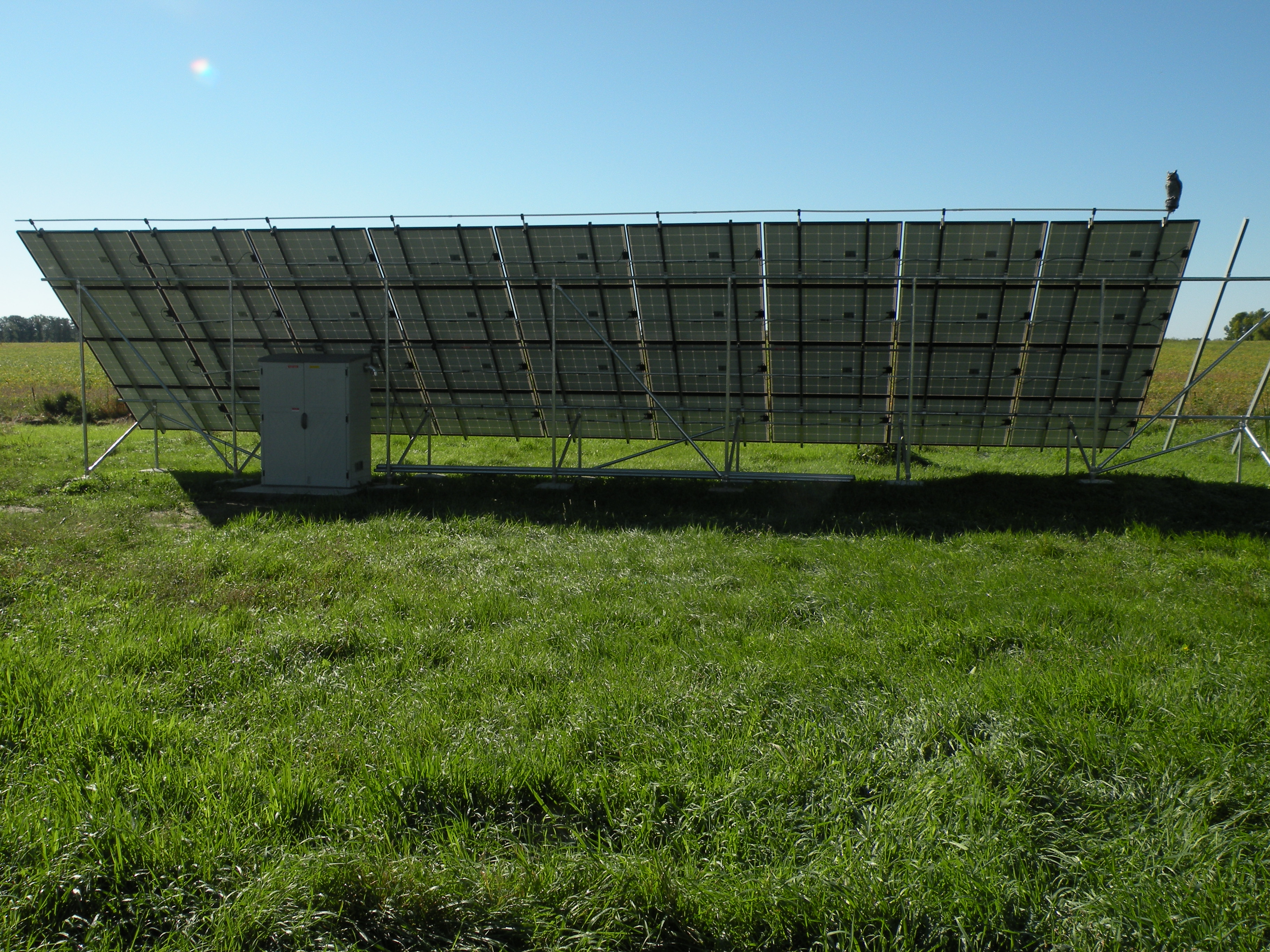
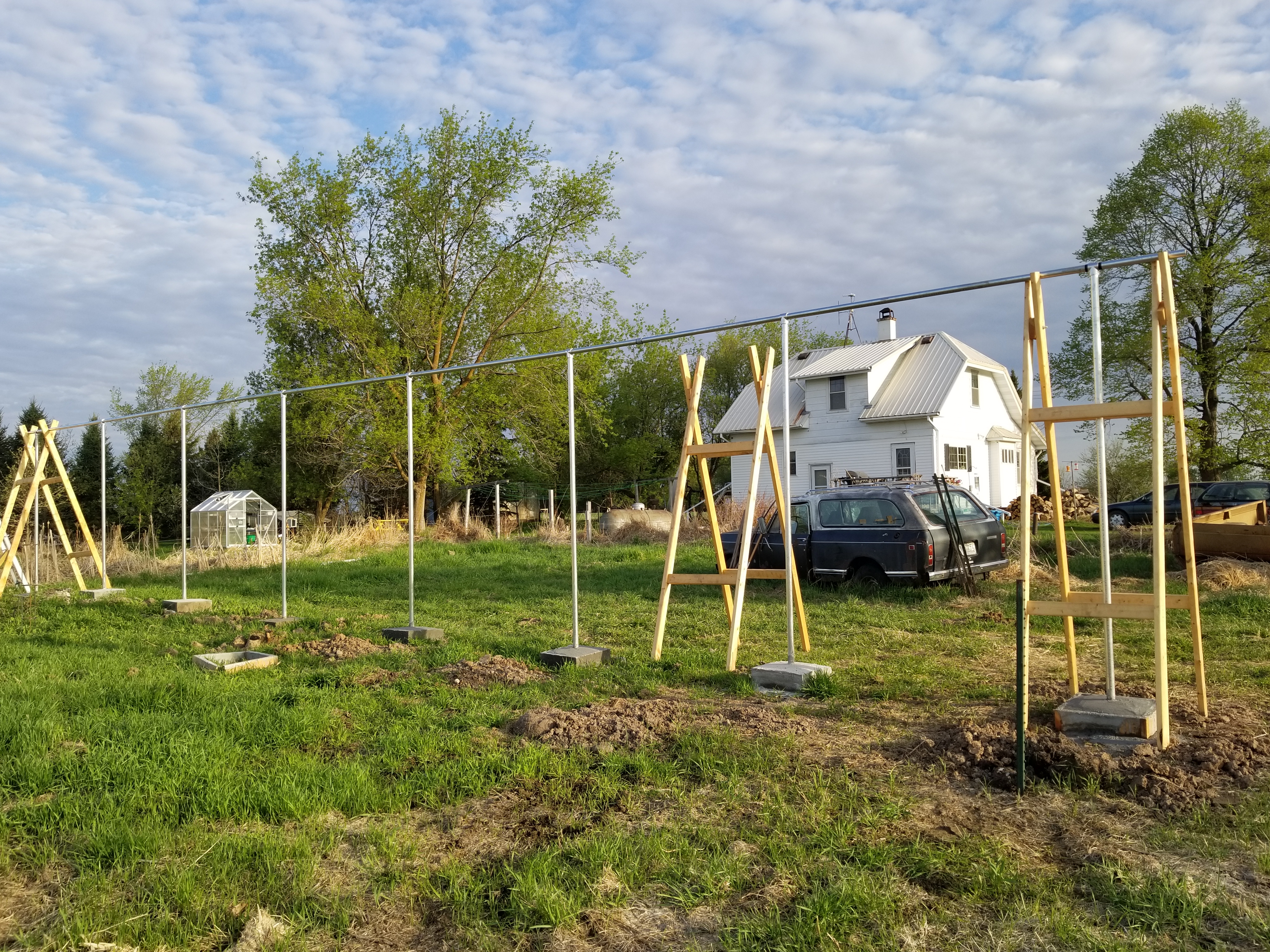
Ground mount piers with bracing. 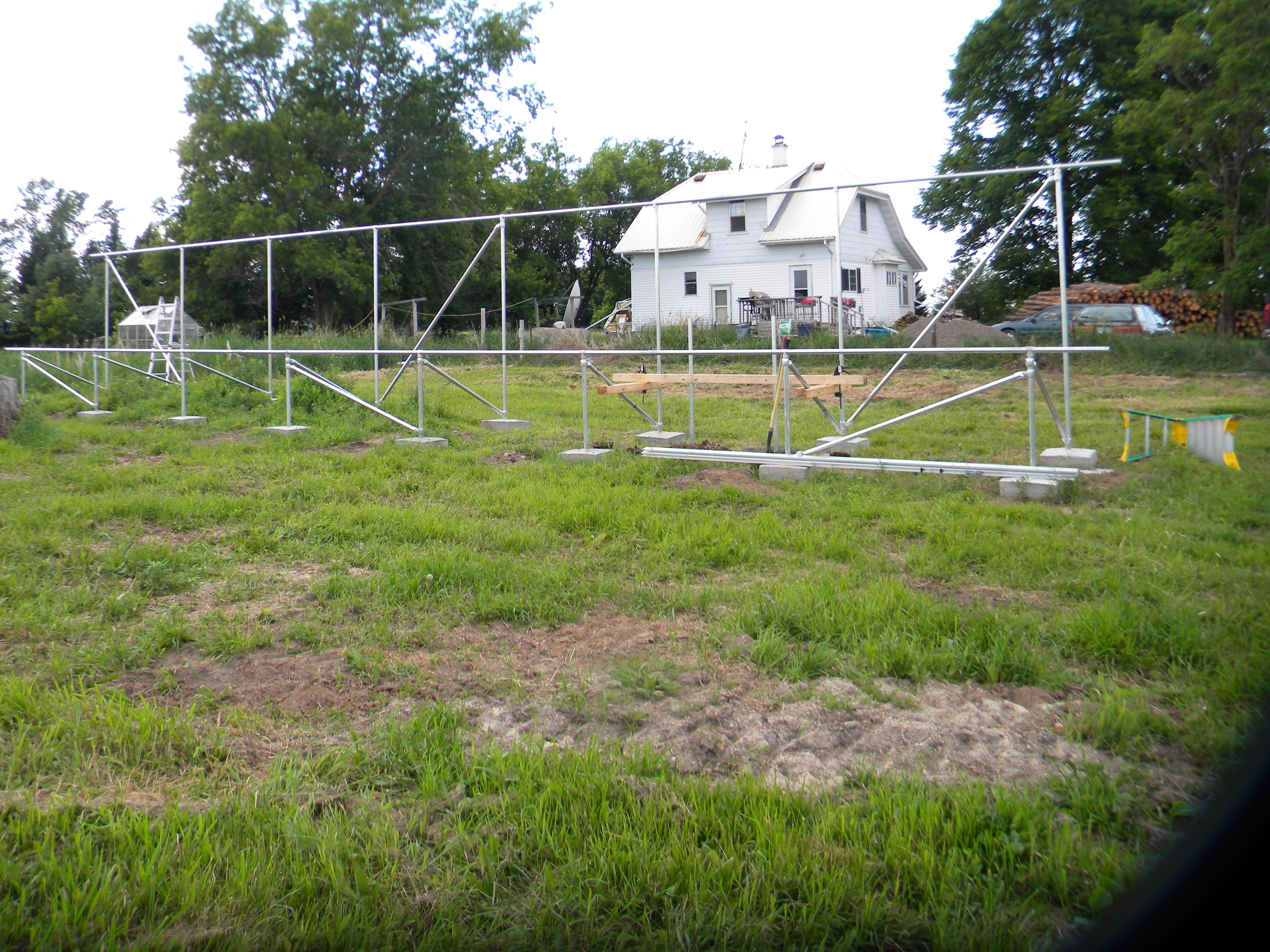
|
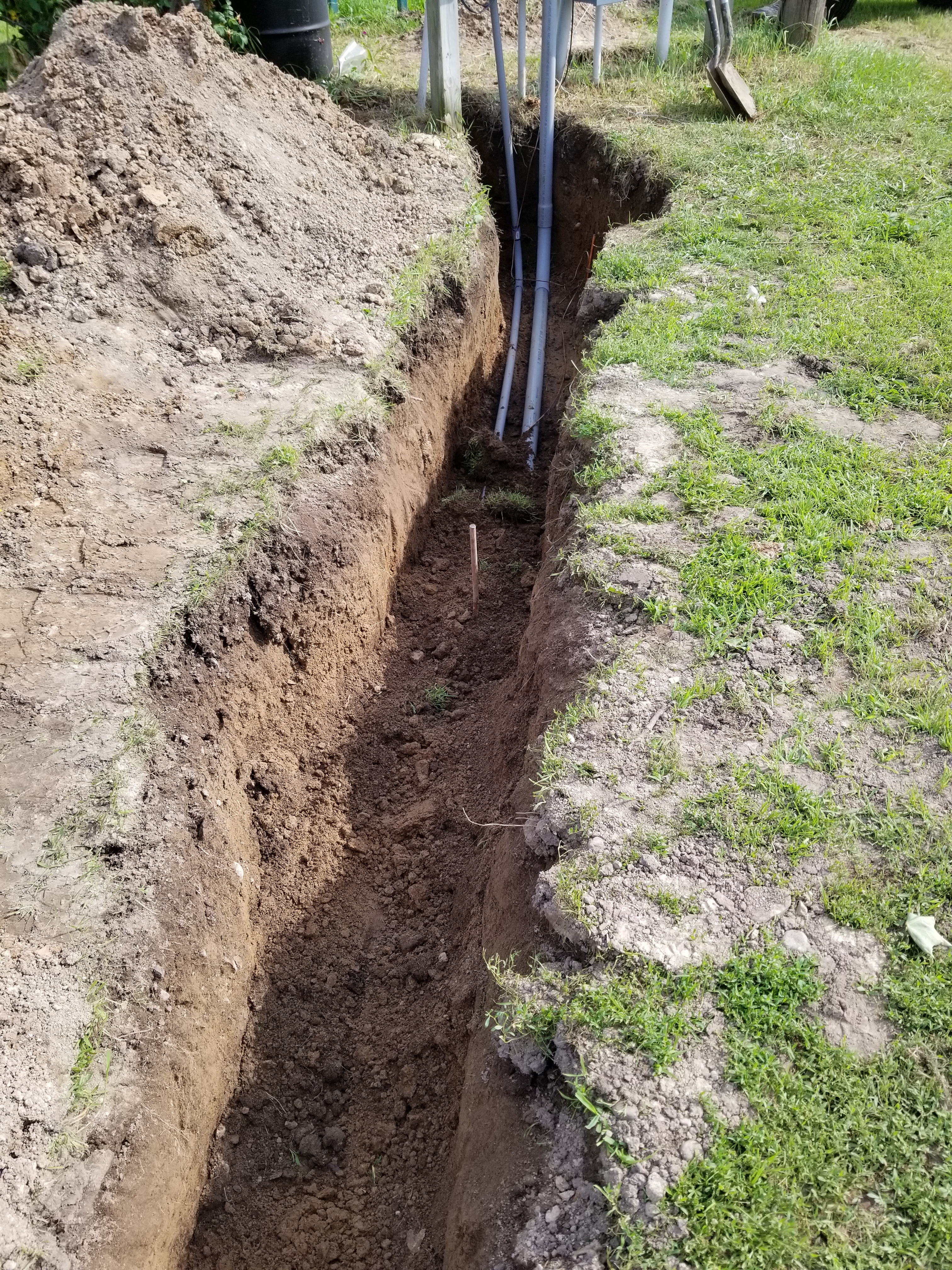
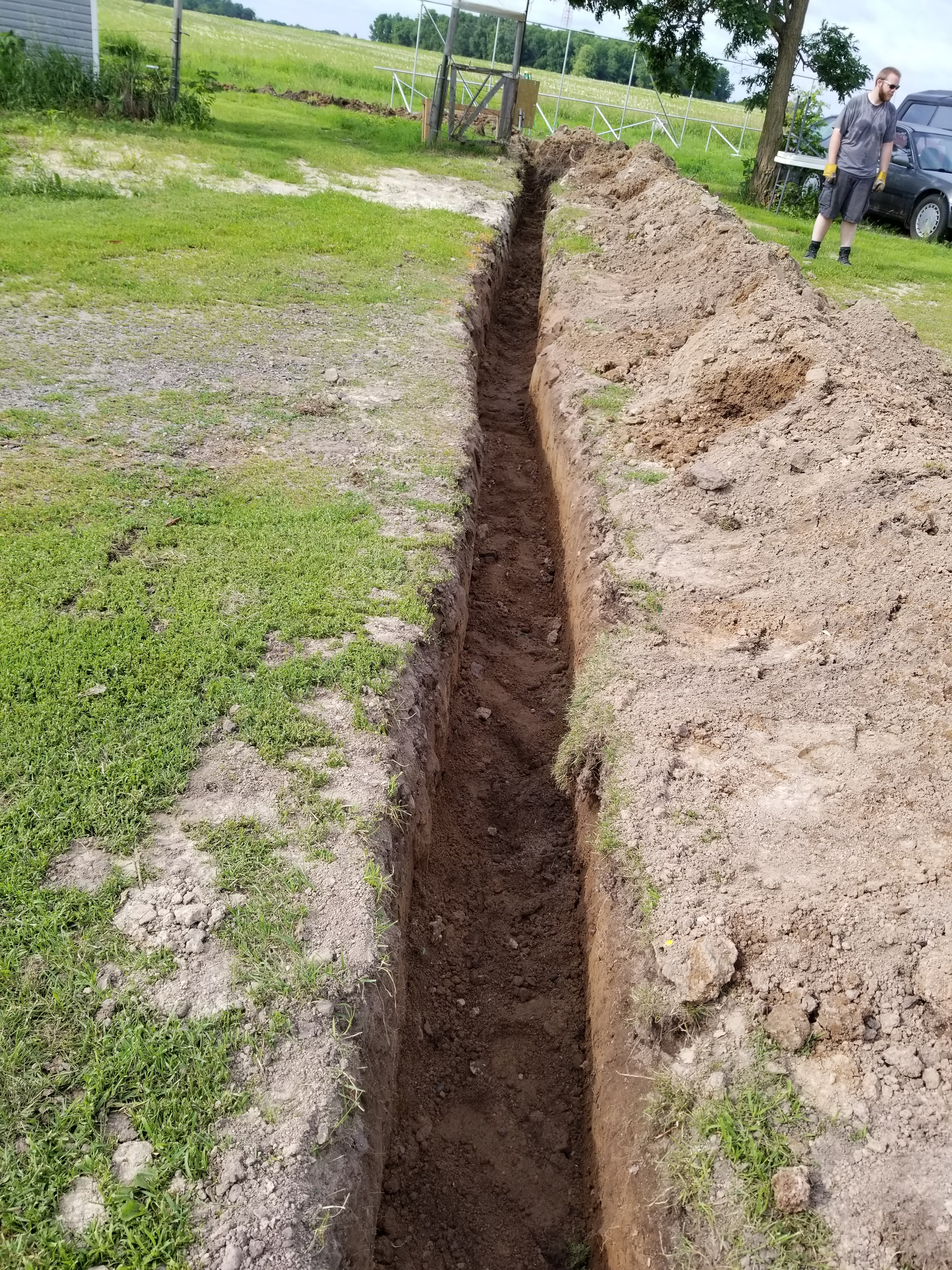
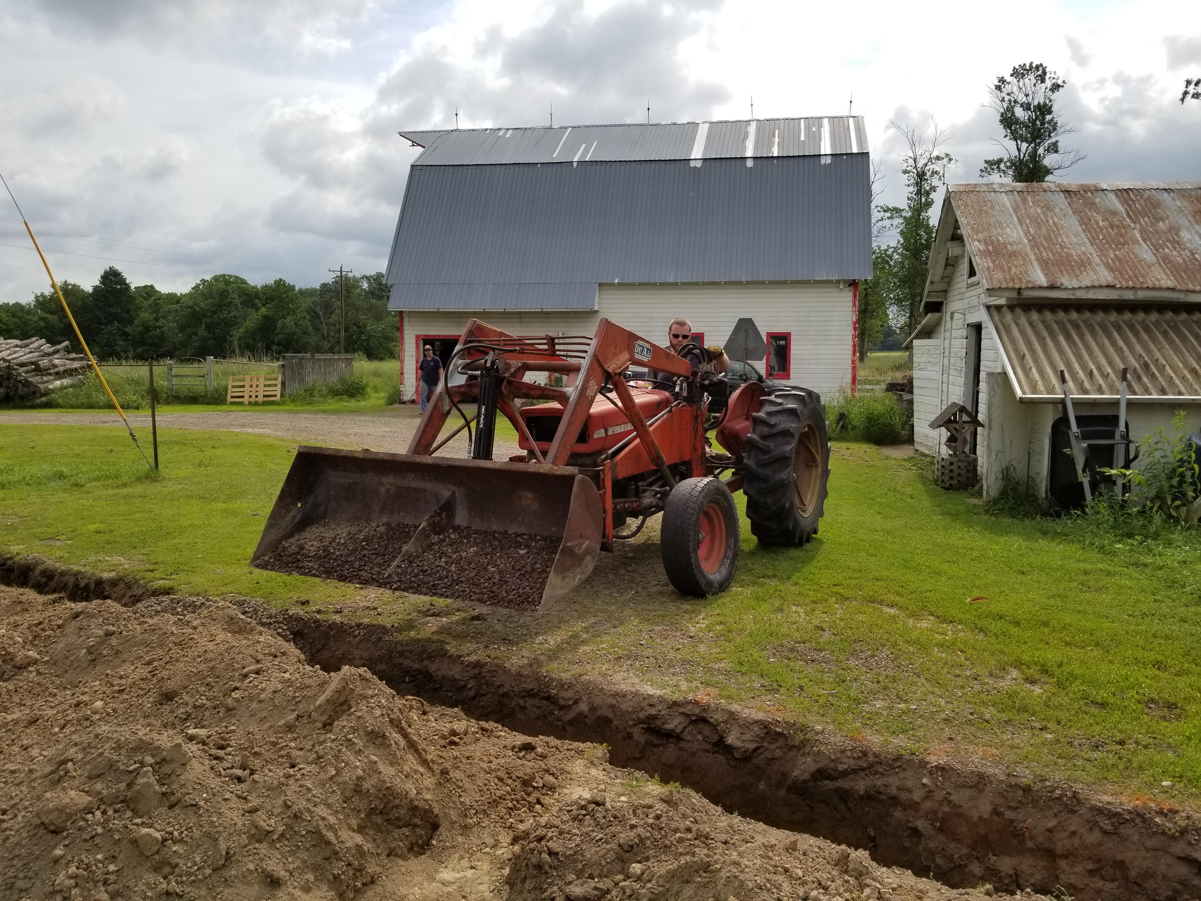
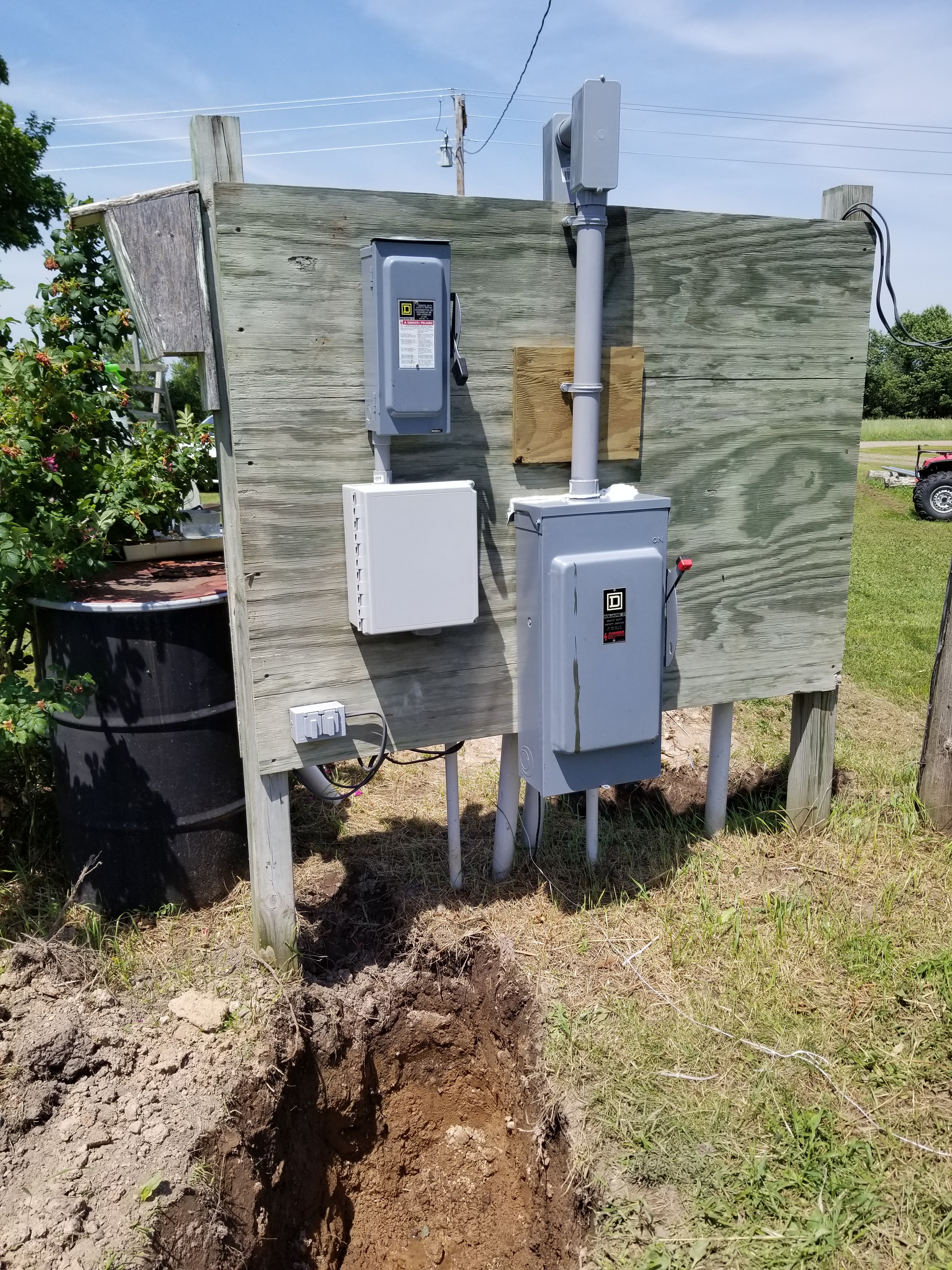
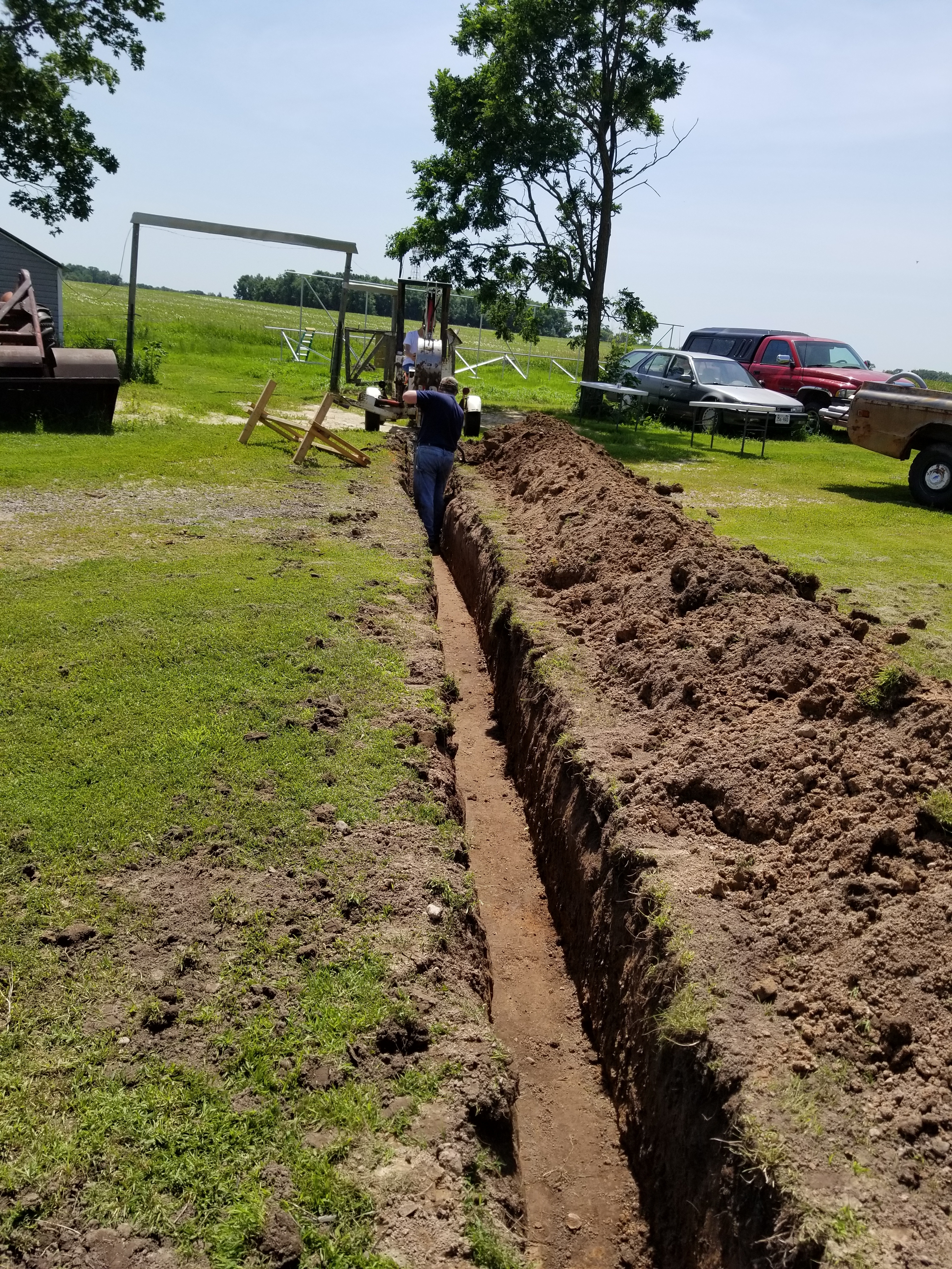
Time to rough in the electrical.
|
|
|
|
|
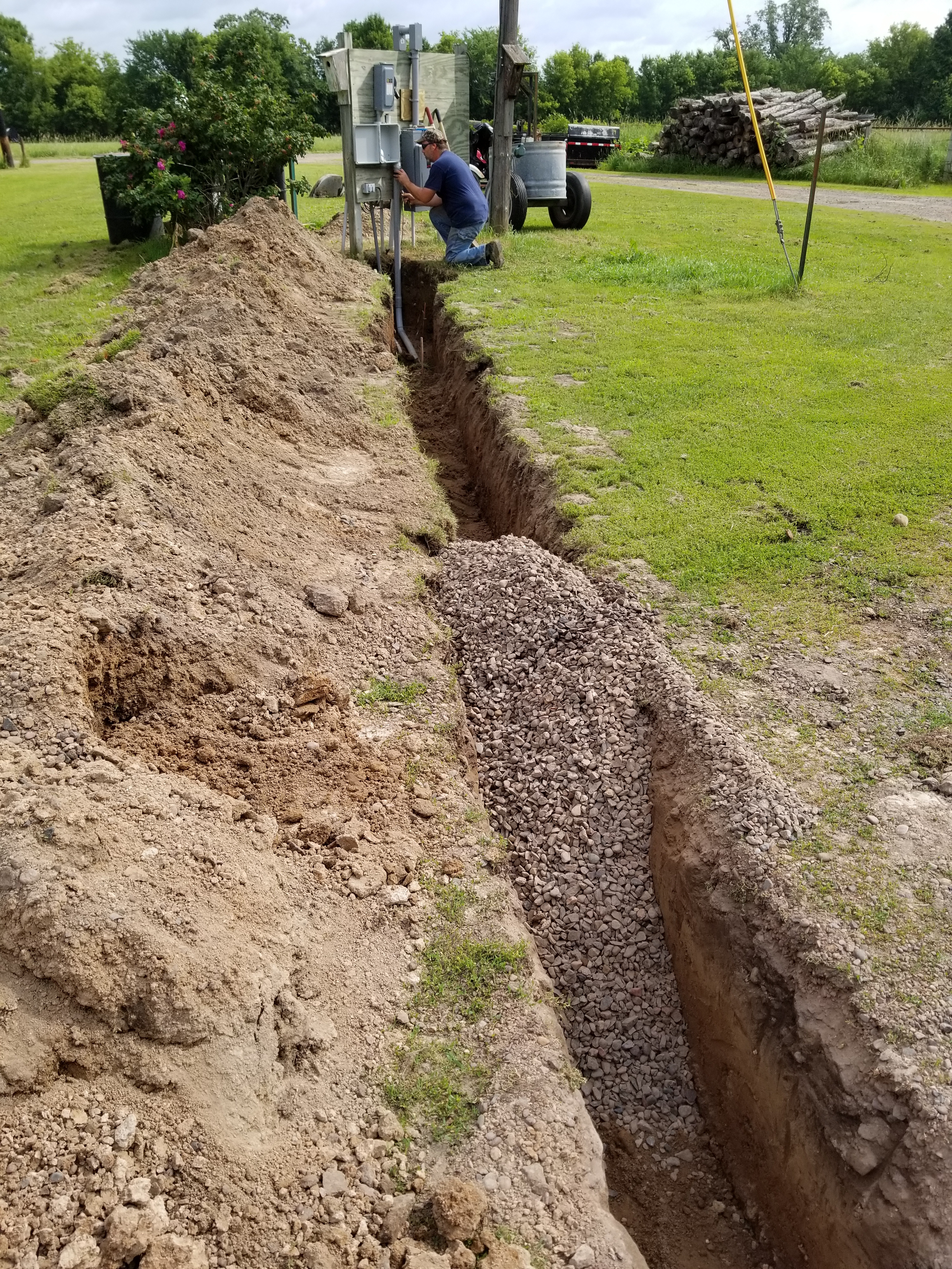
NOTE: Part of the co-generation agreement with Polk Burnett Electric, is that they can come on the property and lock out this switch, any time it is necessary to perform work on the grid. The box on the lower left is a junction box that is serving more or less as an adapter, sizing down the 2” conduit to 1” which fits the switch box without modification. There are many ways we could have downsized the conduit. I chose the junction box so that I could leave a loop of extra wire in there just in case I need it in the future. The Box mounted lower on the right side is a disconnect switch that completely shuts off the power coming from the grid. I installed that more for personal preference, and protection then necessity. |

|
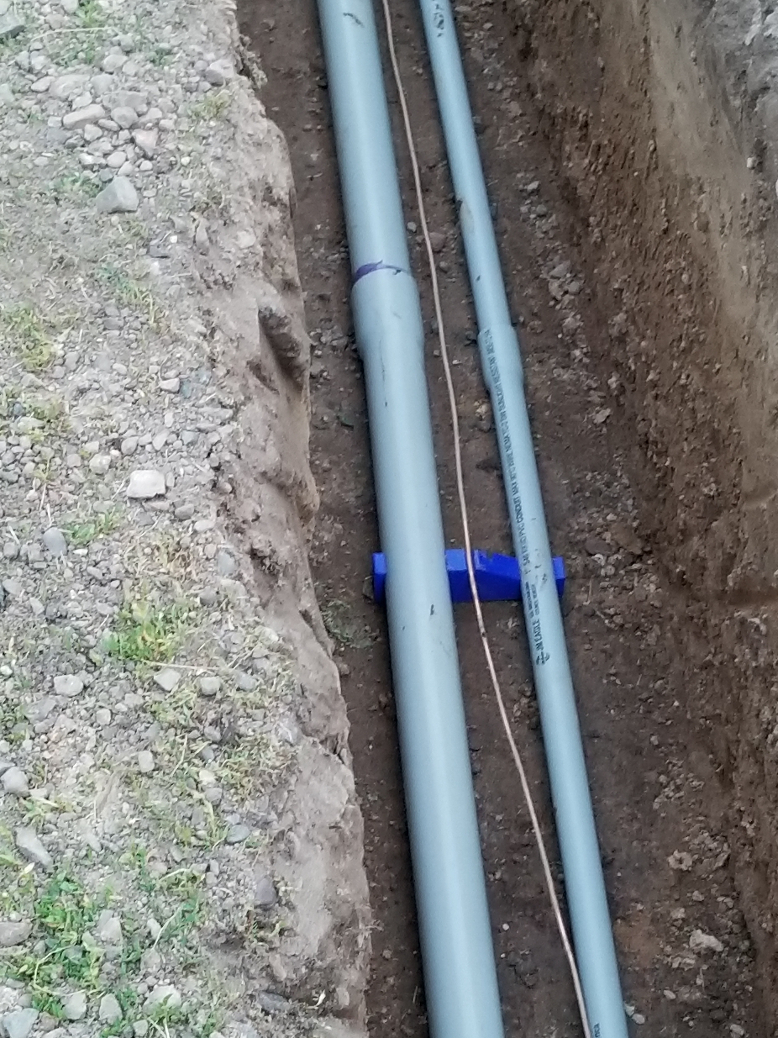
|
|
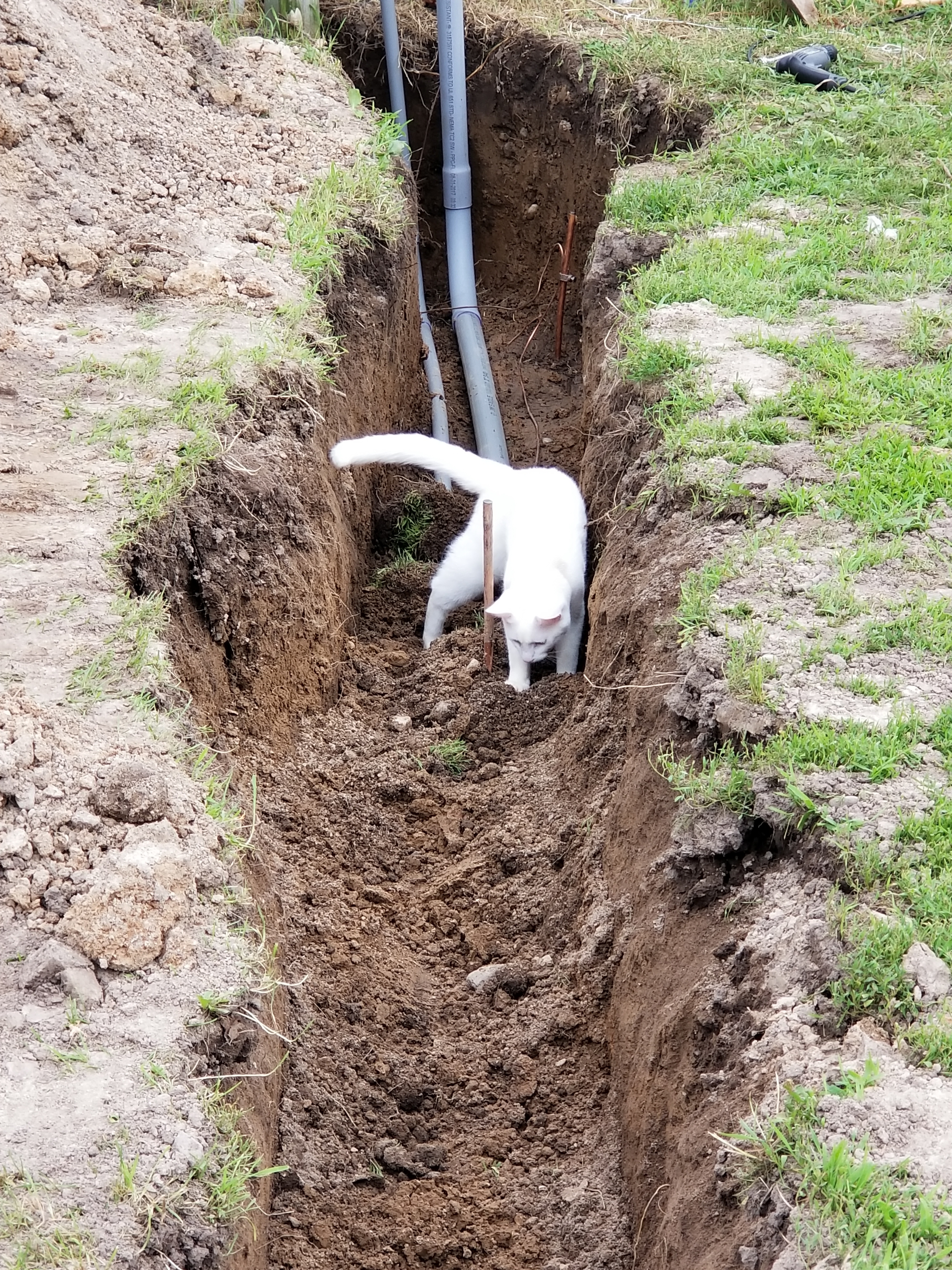
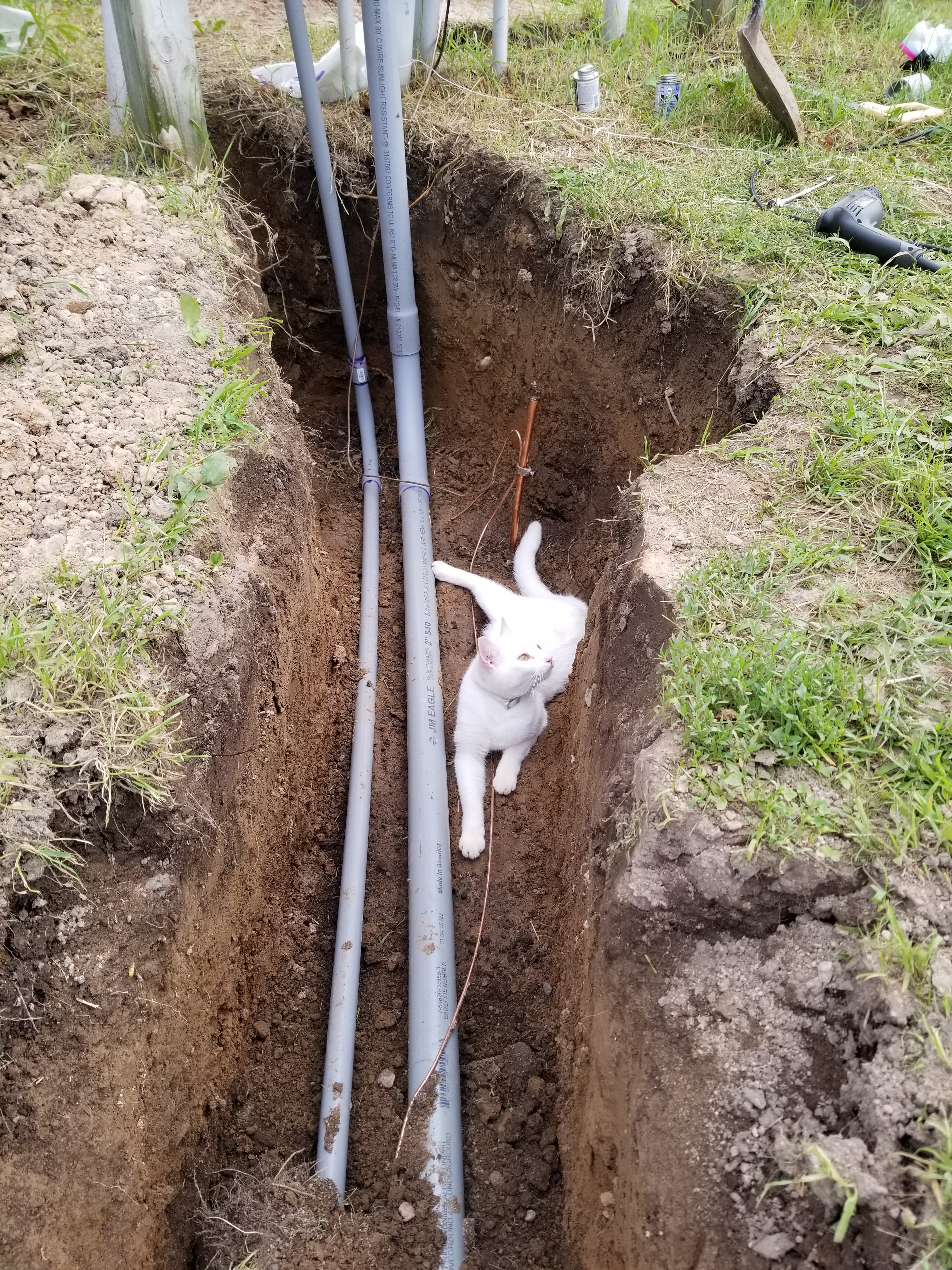
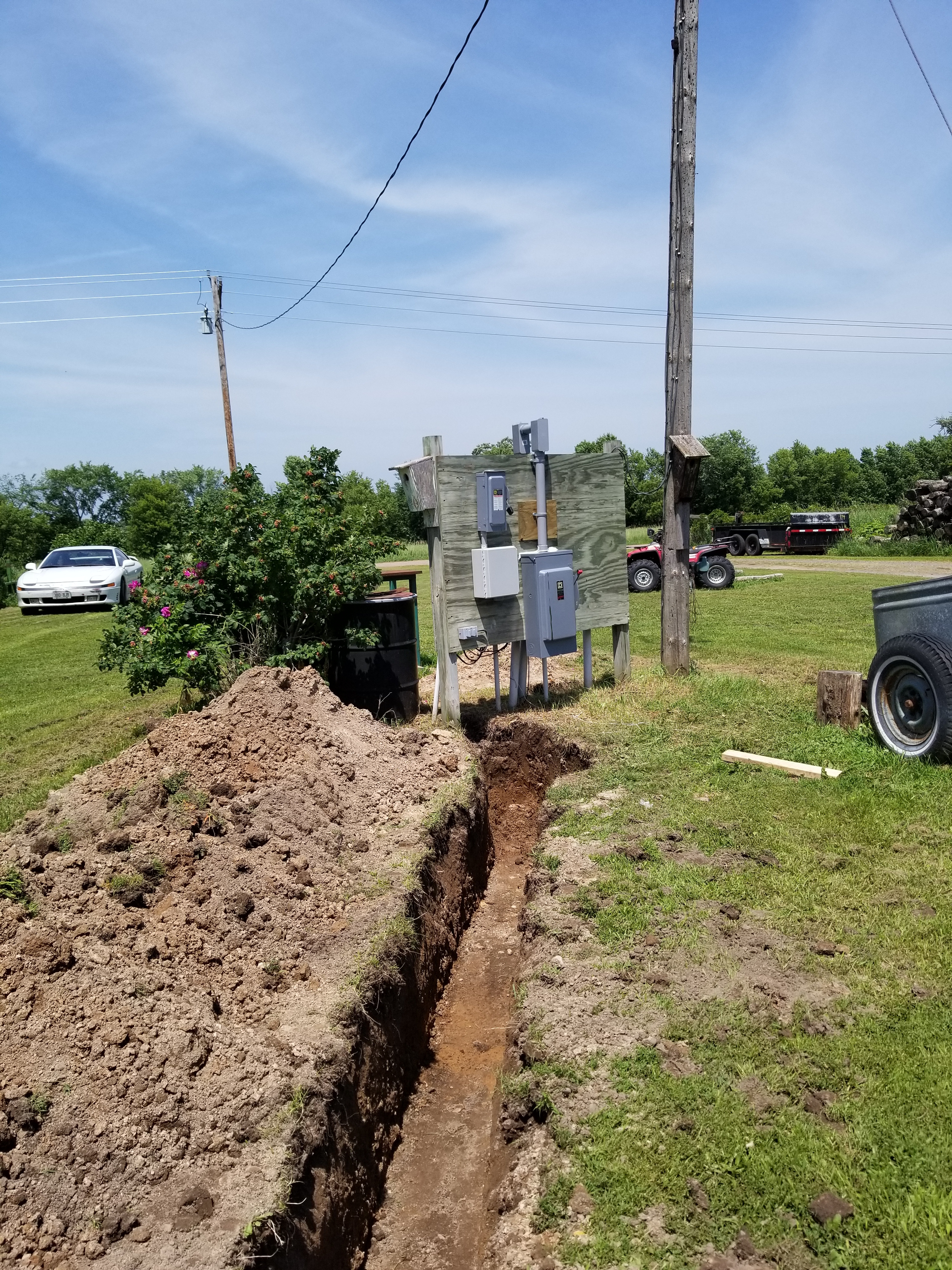
NOTE: Please don’t throw caution to the wind here. Call to have any underground systems located before you dig. |
|
|
|
|
|
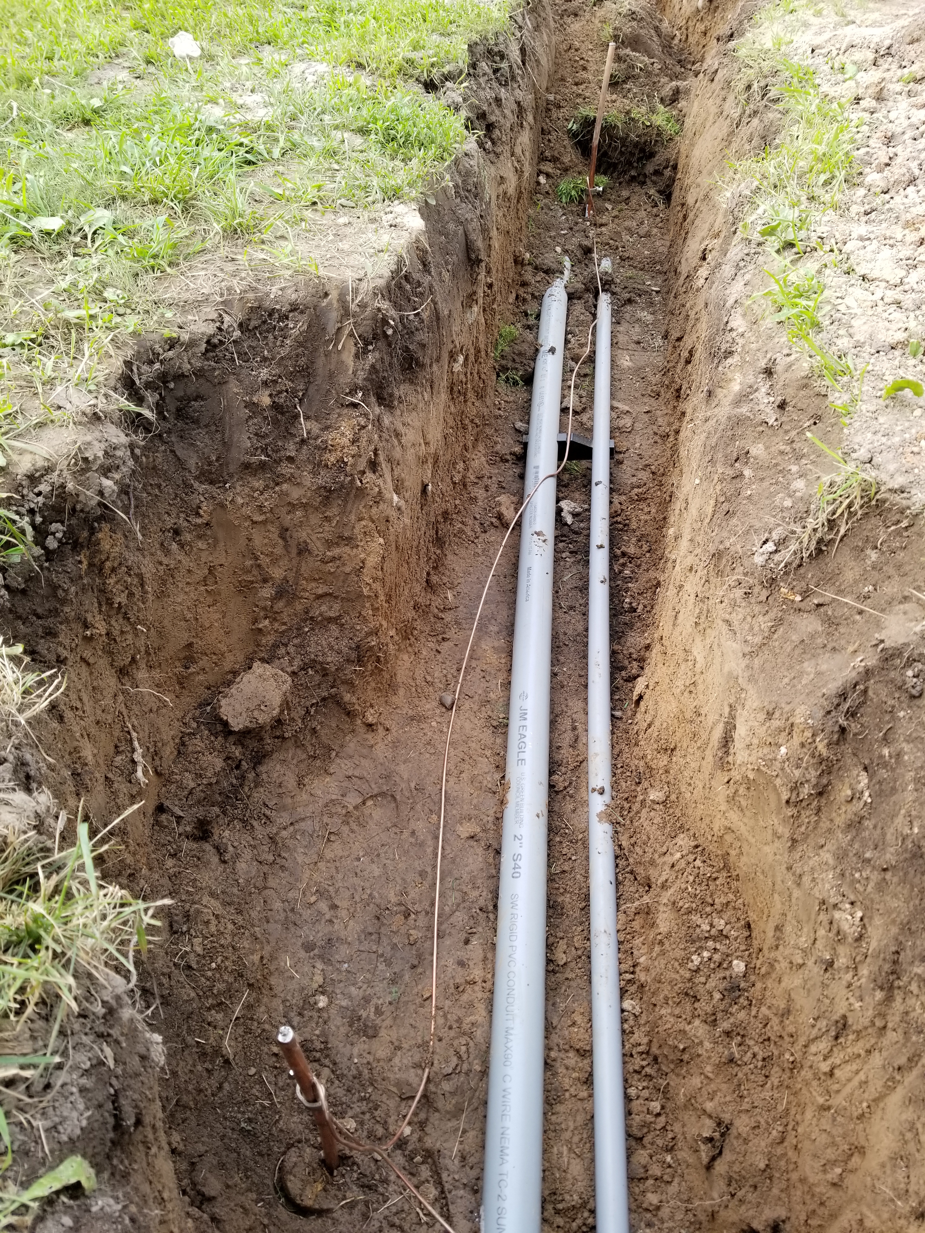
Why is grounding important? Properly grounding your system has much more to do with preventing the lightning strike instead of arresting the lightning after it hits. If an electrical system does get hit by lightning, there is very little that can be done to protect or arrest the electrical currents as the voltage generated by the strike drains off. A properly grounded system tends to drain the potential differential energy in a controlled manner, and thus hopefully prevent the lightning strike from ever happening. |
|
|
|
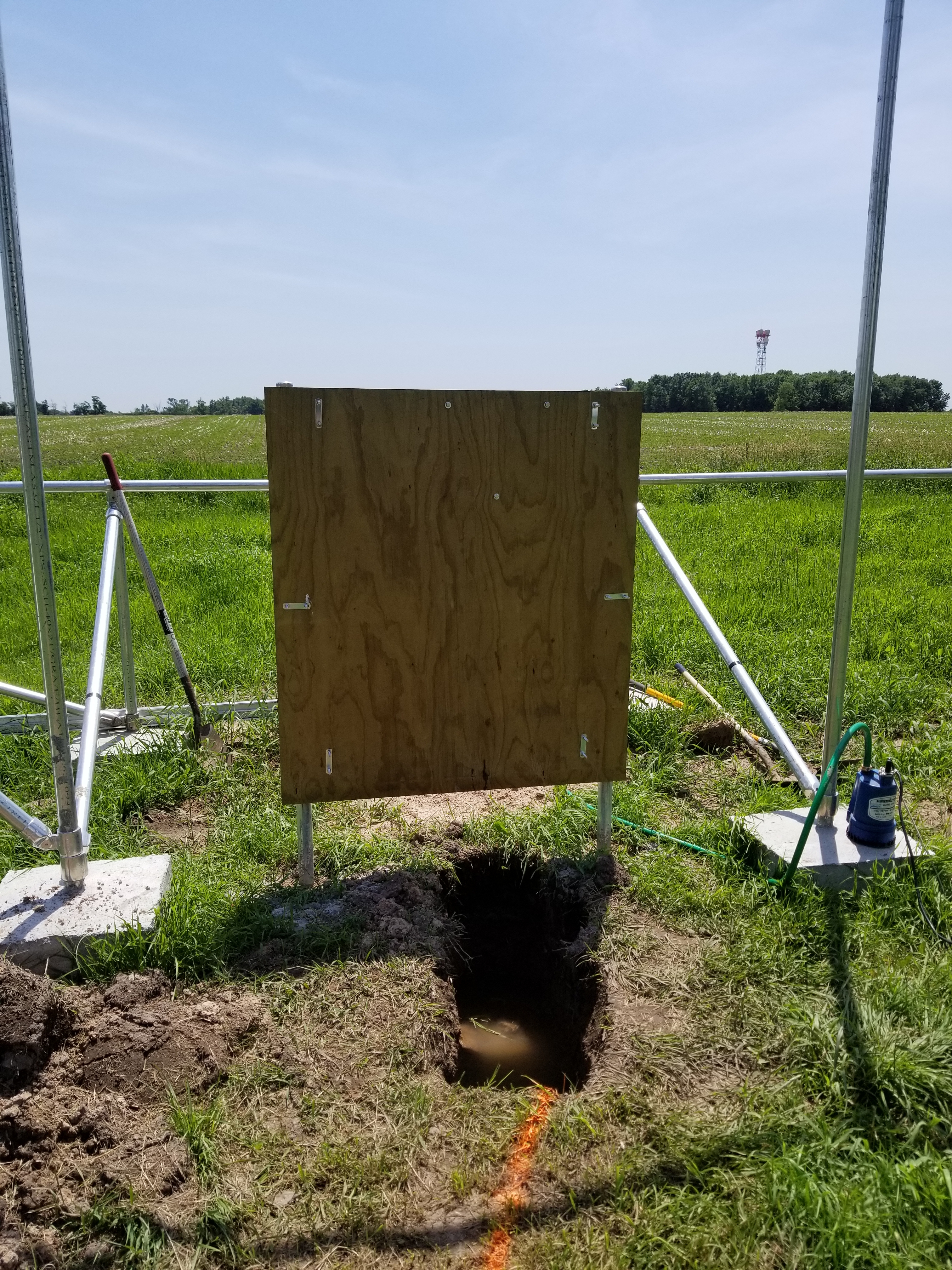
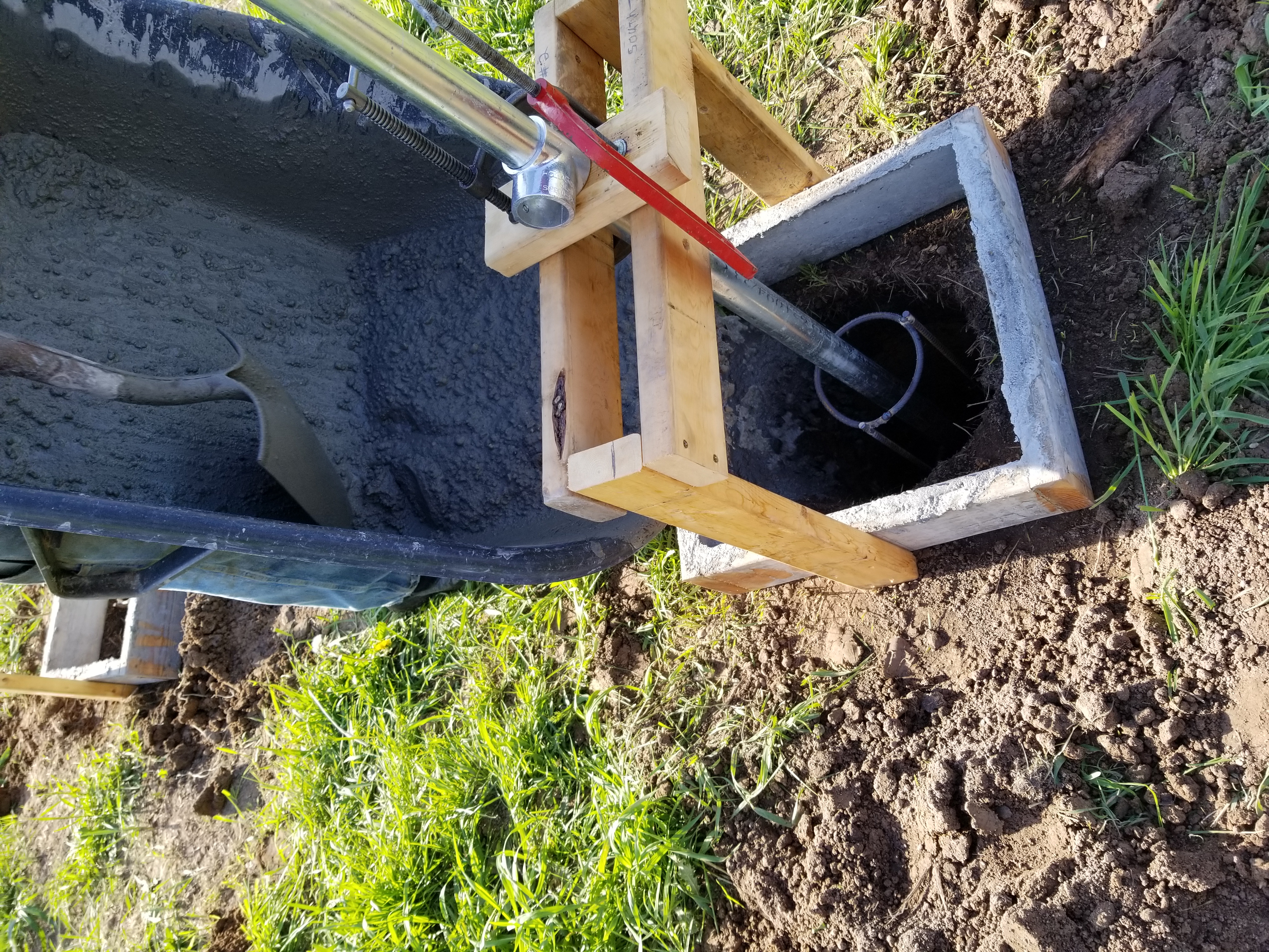
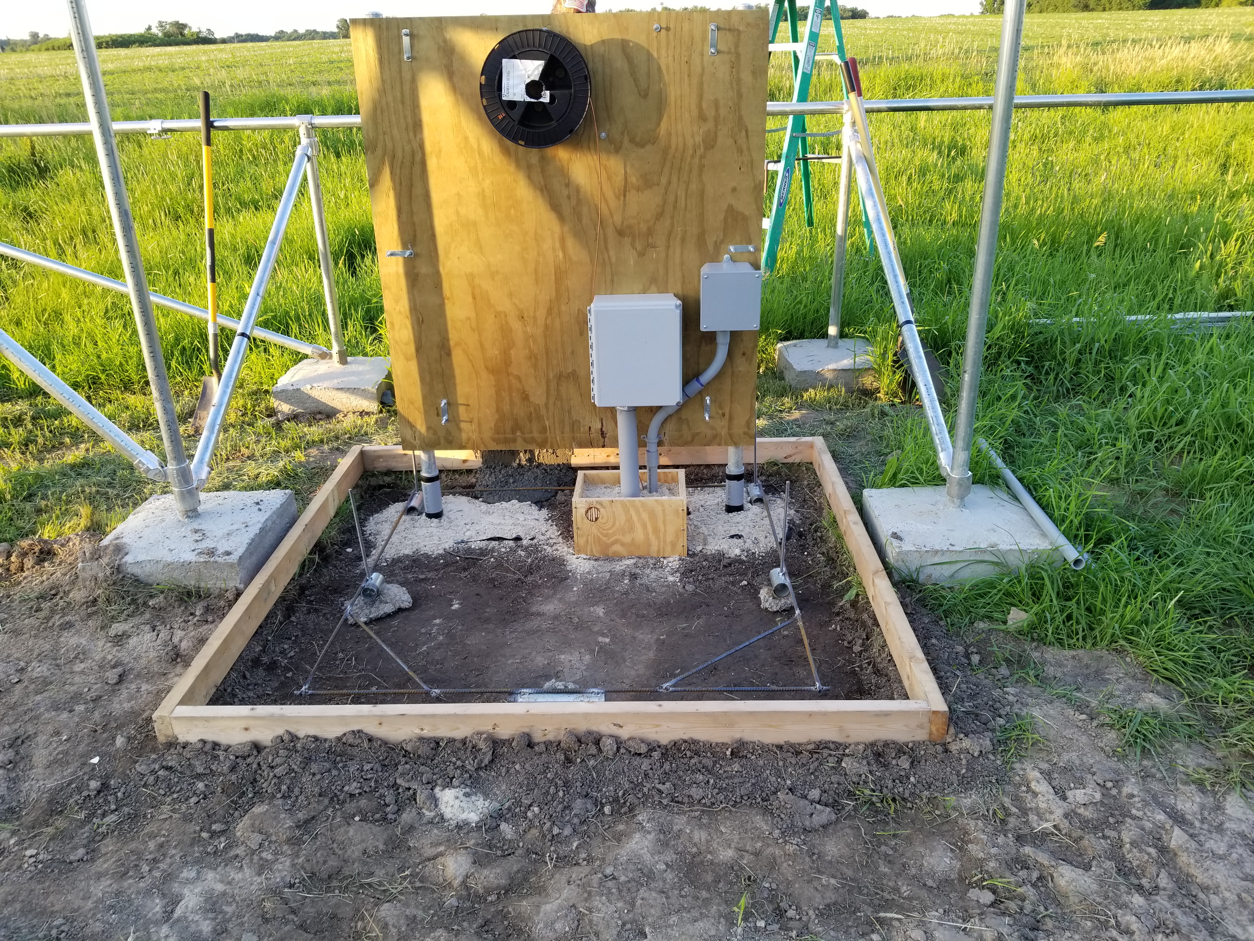
NOTE, the small wood box, around the conduit, and the short pieces of PVC around the two poles. The idea here is knowing that the cement slab is going to move around a little bit, due to the frost, we are hoping to isolate the slab from the poles and the conduit to allow the slab to move without putting pressure on the poles and conduit. We’ll see in a few years how that all works out. The PVC was a cut from an extra piece of conduit that I split in half with a hack saw. I then taped it back together around the poles with electrical tape. The re-rod has vertical threaded rods welded to it to eventually bolt down the ‘Fronious Closet’. |
|
|
|
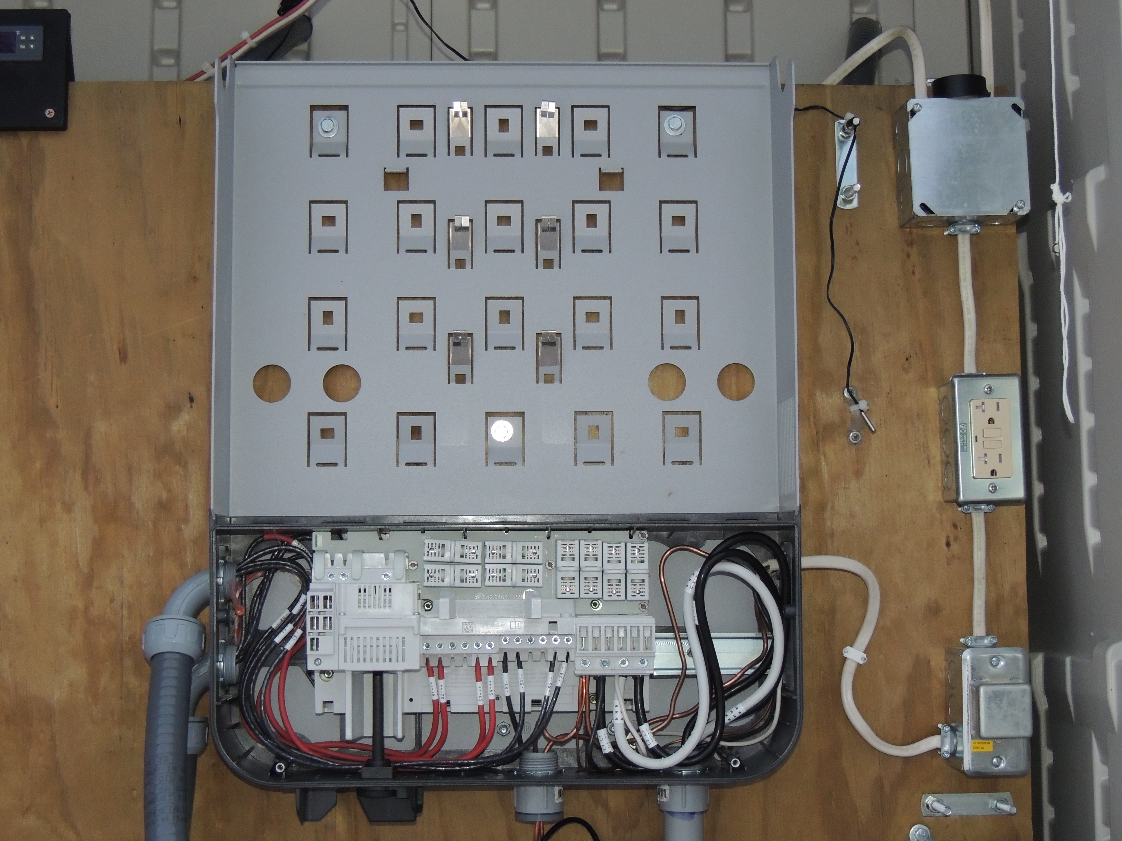
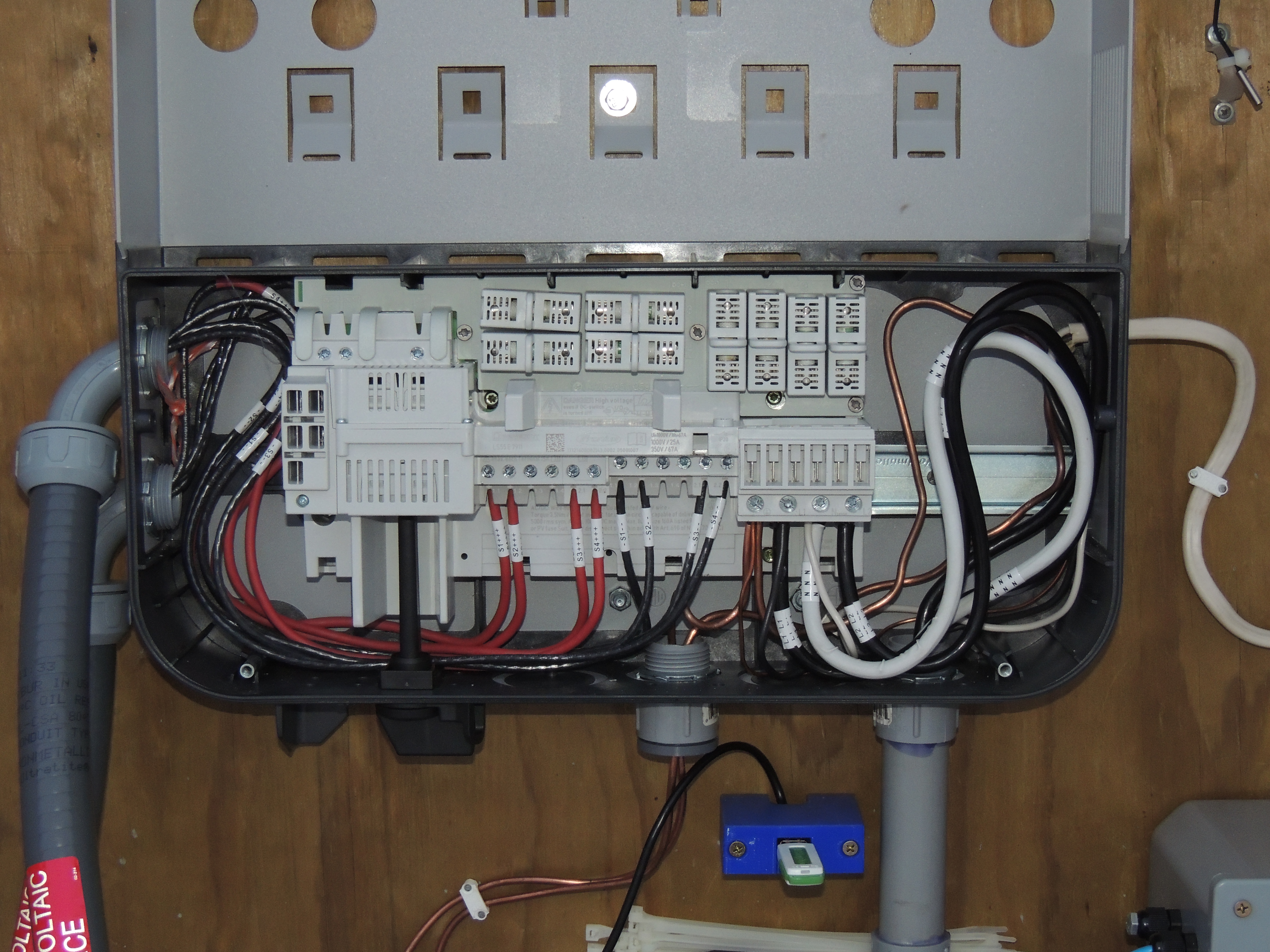
The large box with the exposed wiring is the mount for the Fronius solar inverter. The D.C. voltage comes in from the solar panels on the left side. The RED wires are simply black wires covered with red heat shrink to differentiate the positive and negative leads. The A.C. voltage goes out the right side. The large WHITE wire again, is simply a black wire with white heat shrink, to show that it is the neutral wire. The large bare wire is of course the #6 awg ground wire that I mentioned a few pictures up. The smaller wires are the ‘Hot’ (L1) neutral and ground of the small branch circuit to supply power to the outlets and fan. |
Let’s Get’r Done!
|
|
If you look closely, you will see some black electrician’s tape at the bottom of the rail. We placed and measured a rail at each end. Then we ran a string line from across the bottom of the two outer rails to create a reference point to keep the rest of the rails in line with each other. Since the end of the aluminum rail was rather sharp, I taped it up with some electrical tape first, to prevent cutting the string line. |
|
The rails are all in place, to the lower left is my homemade square that we used to align the rails. |
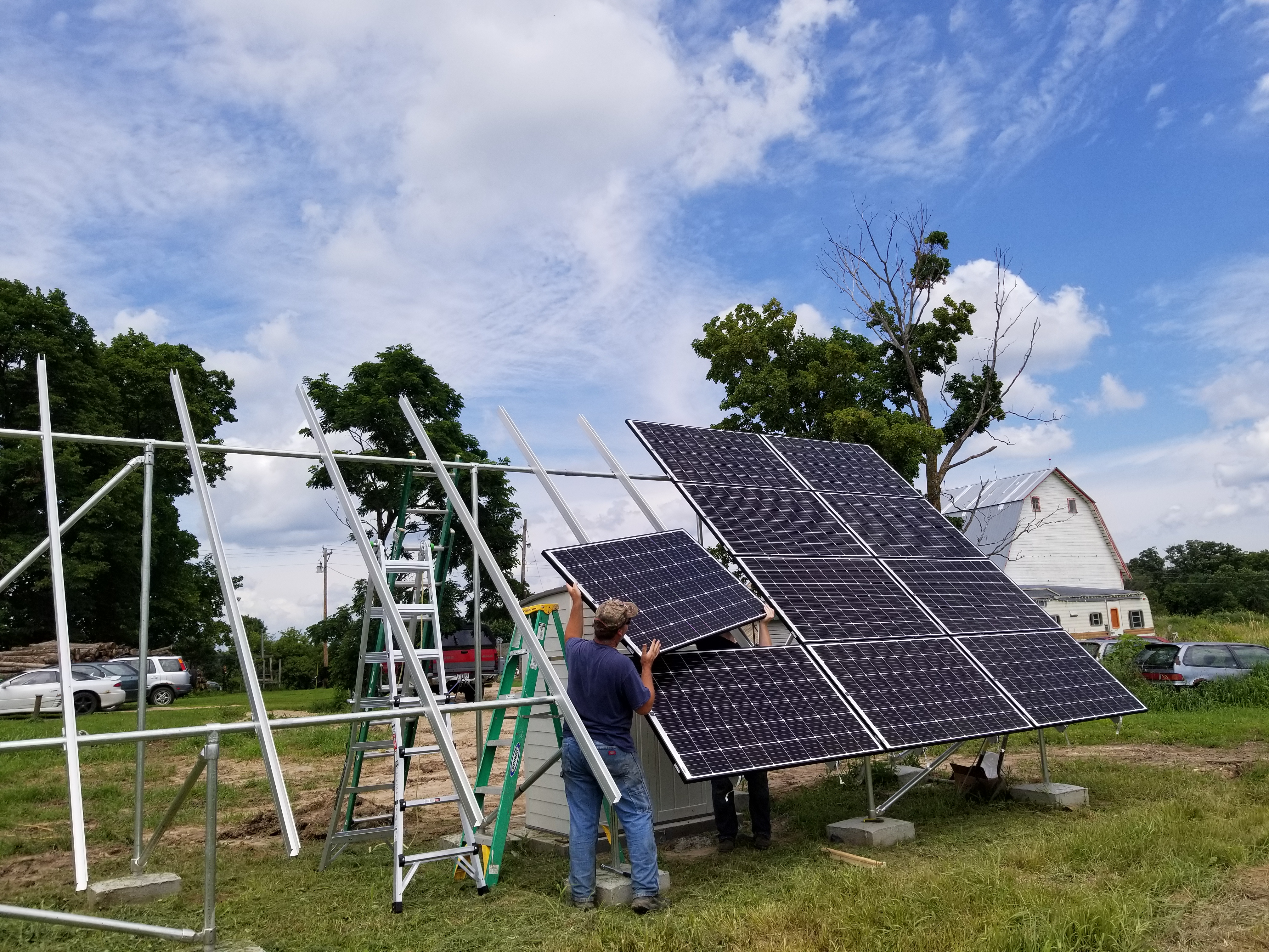
If you look closely toward the bottom center, you can see my crude but effective spacer that we used to set the 1 inch gap between the panels. |
When we set each bottom panel, we used a homemade spacer that consisted of a 1 inch wide piece of scrap 2x4 that I ripped on the table saw, with another scrap board, screwed to the top of it to prevent it from falling through. We used the spacer on the bottom panel only, then we used the red 4ft level as a straight edge to help keep the rest of the column in line. |
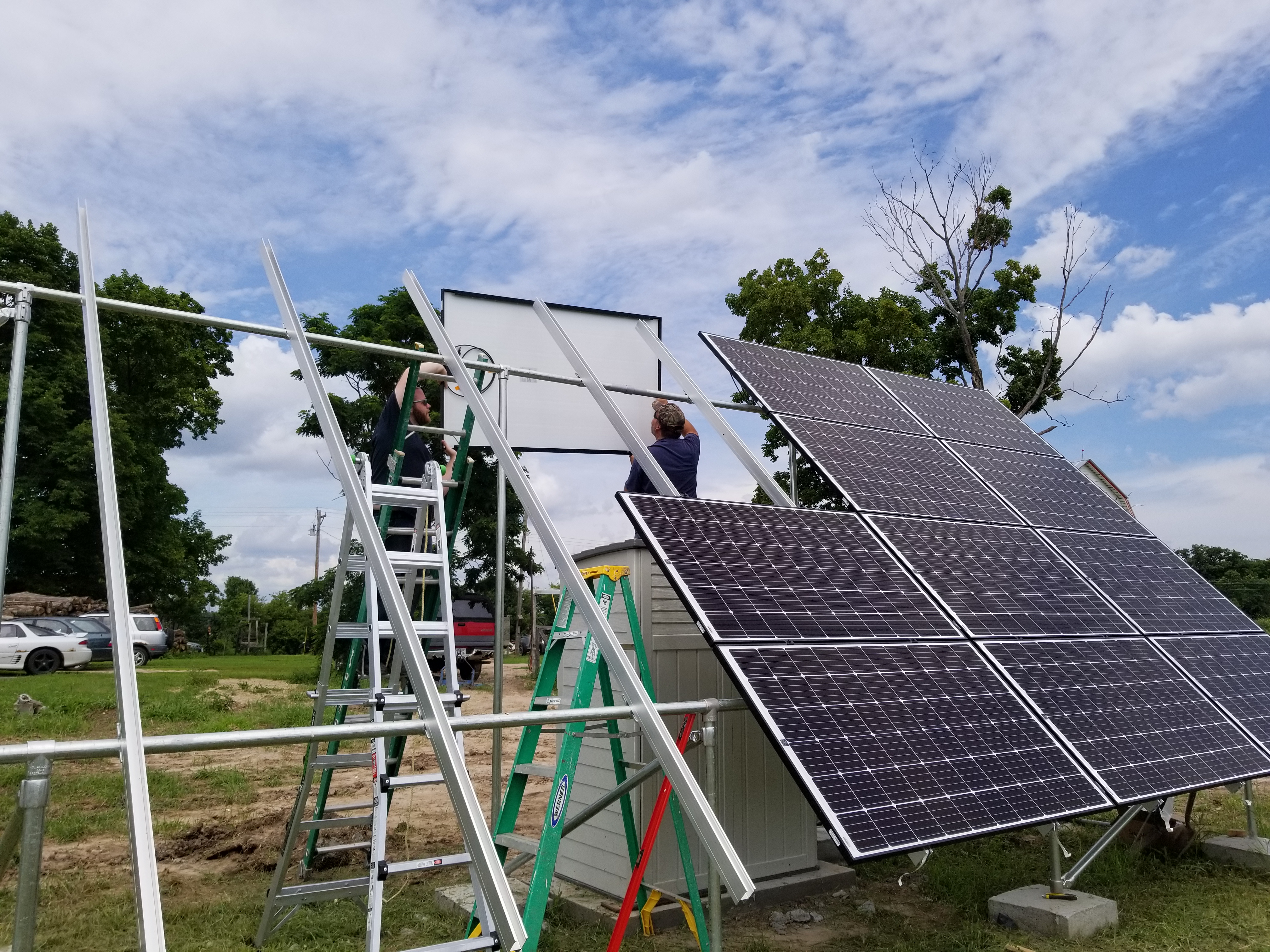 We used the red 4ft level as a straight edge, to slide each panel into place, in line with the panel below it.
|
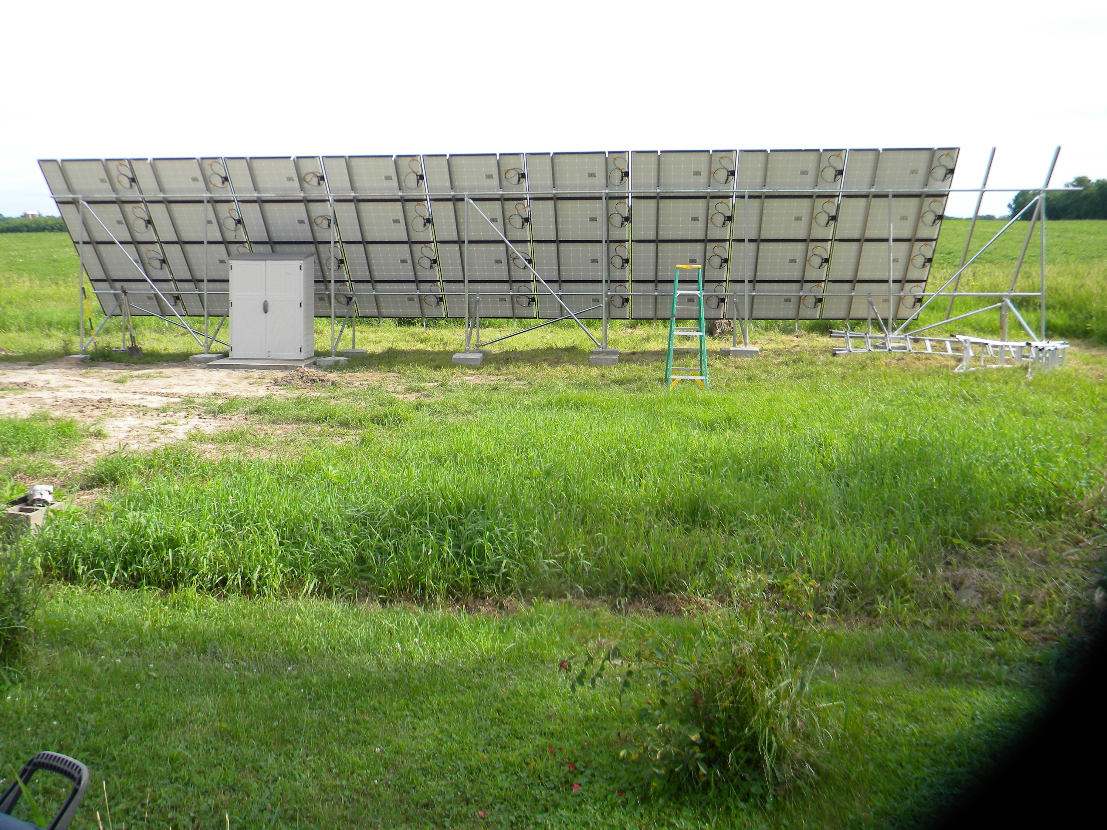
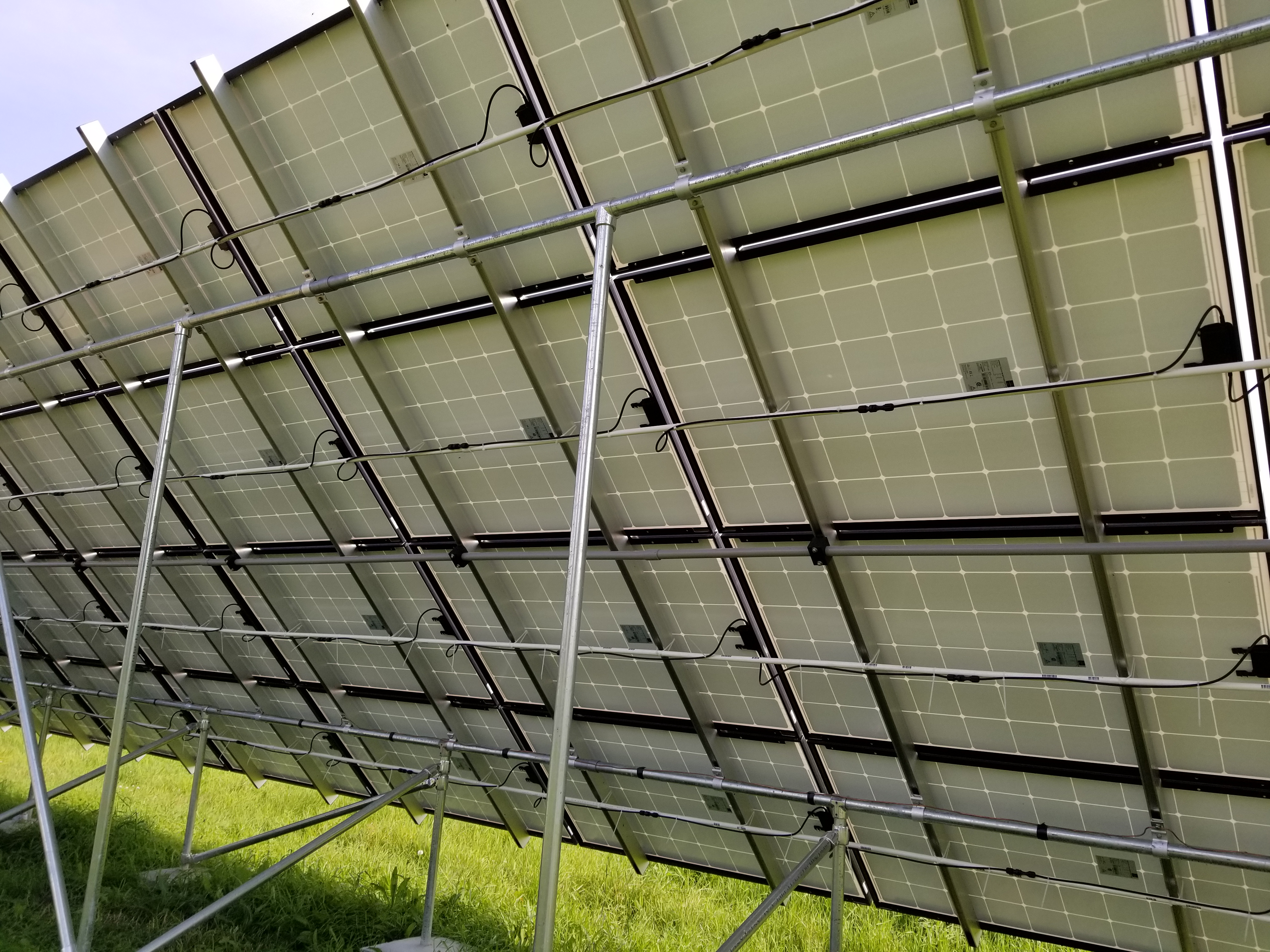
The panels are up, but nothing is connected. The next steps are the “Home Run” lines, and connecting the panels into strings. |
|
 Now that the panels are installed and exposed to whatever comes along, it was time to inform our home owners insurance that we made an addition, and want it to be protected.
|
Let’s make these things useful!
| String Theory isn't just to describe the Cosmos |
|
|
| Home Runs aren’t just for Baseball anymore! |

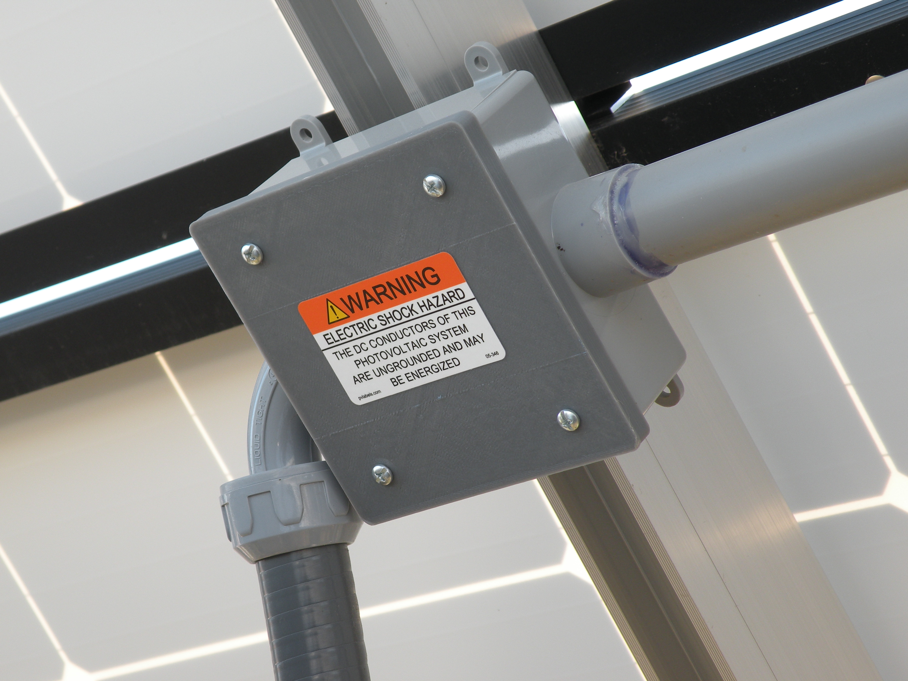
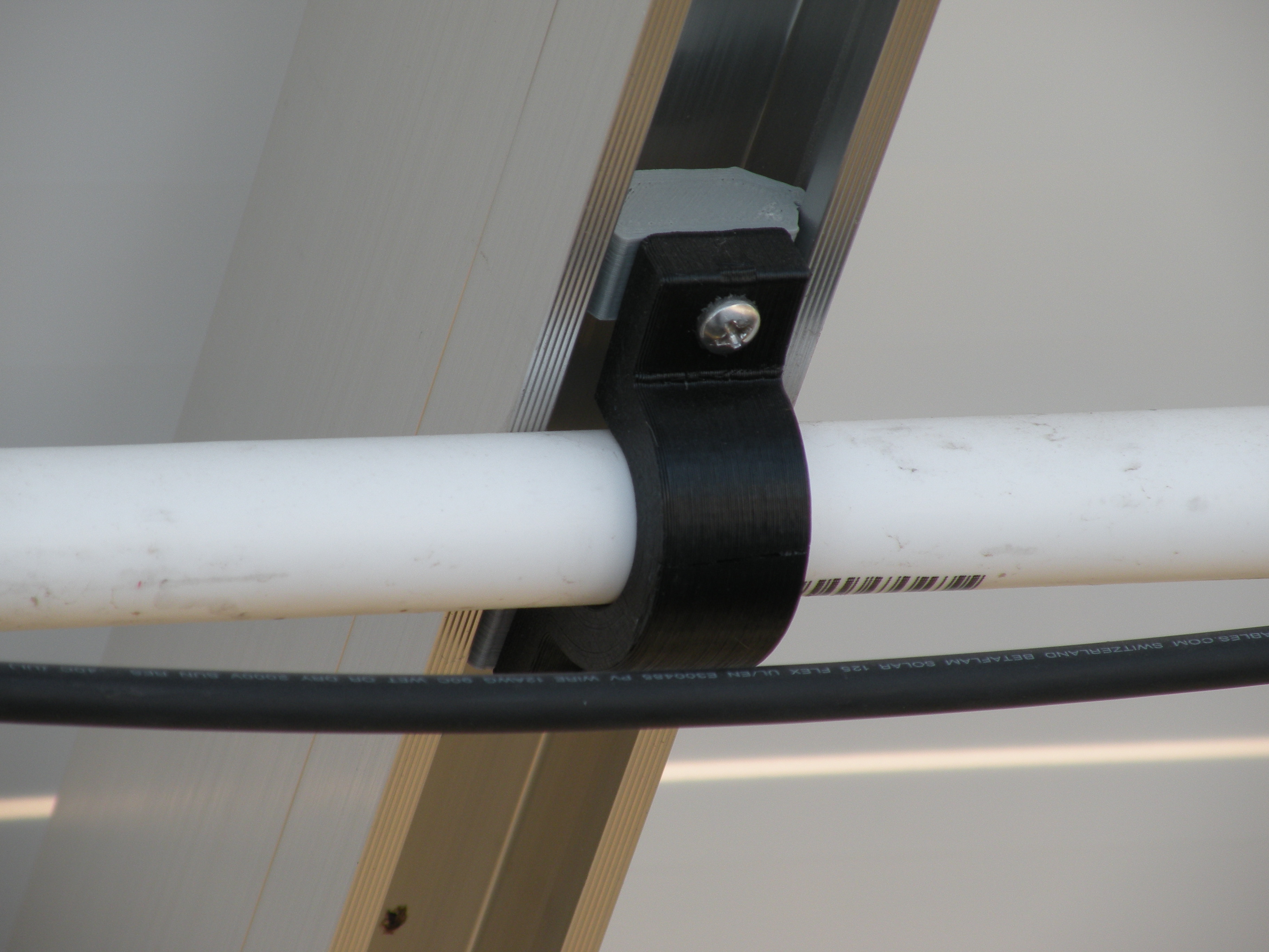
These are the Home Run conduits leading to the junction box that transition to the flexible conduits that go to the Fronius inverter. These conduits are anchored to the back side of the panel mount rails using the snap in bolt mounts, and the conduit clamps that we 3D printed. |
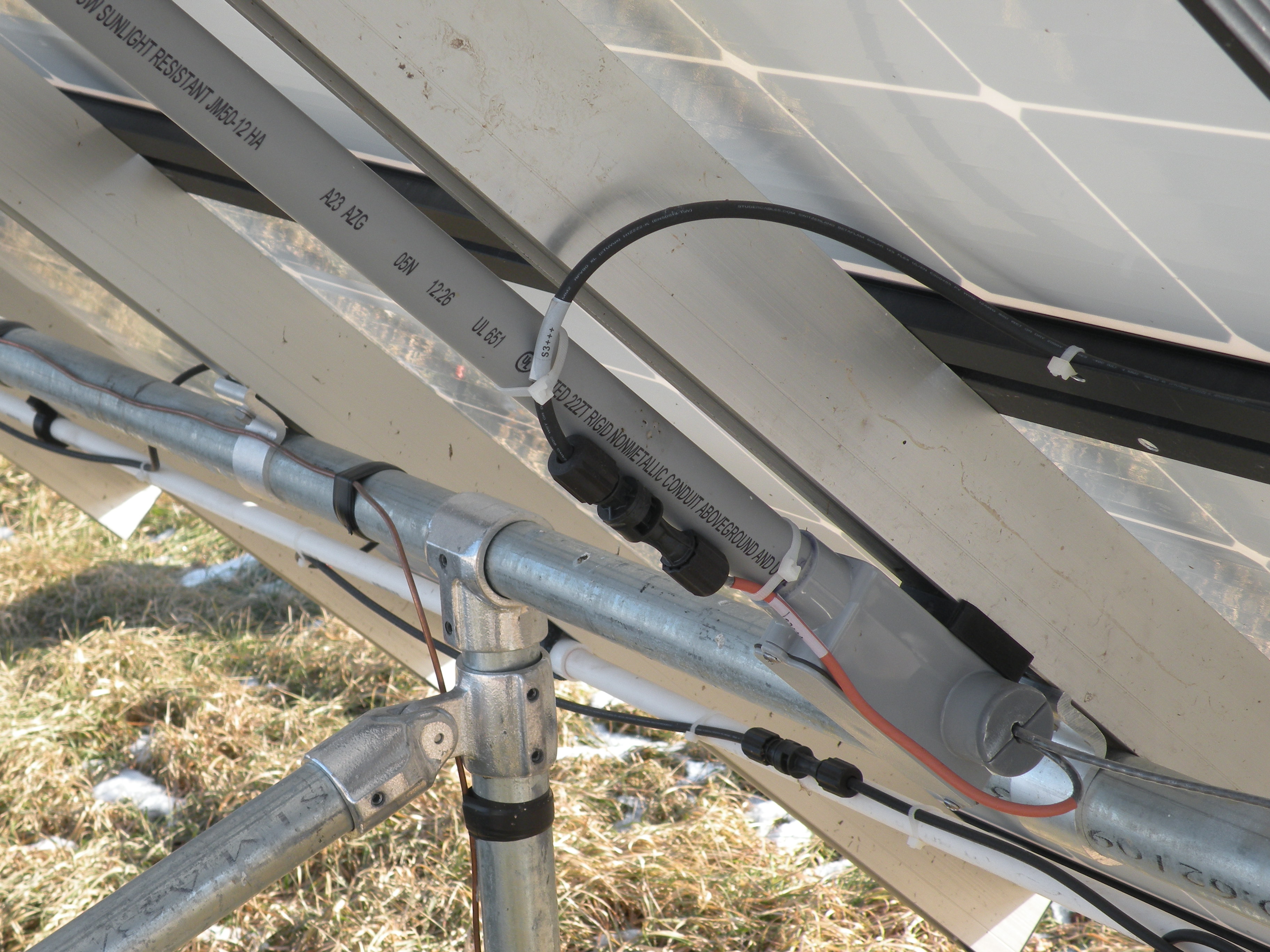
If you look closely at the picture to the left you can see the conduit ends at a TEE fitting. We used the TEE fitting to extend to end fittings where we brought the Home Run lines into the conduit. We printed the plug below to serve as kind of a grommet. We simply ‘glued’ them in with silicone sealer. |
snap-n-rack_conduit_pad_01.stl This printed spacer was used with the snap in rail anchor below, to mount all of the conduit fittings, in order to stand them off of the rails the same distance that the conduit clamps hold the conduit off of the rails. |
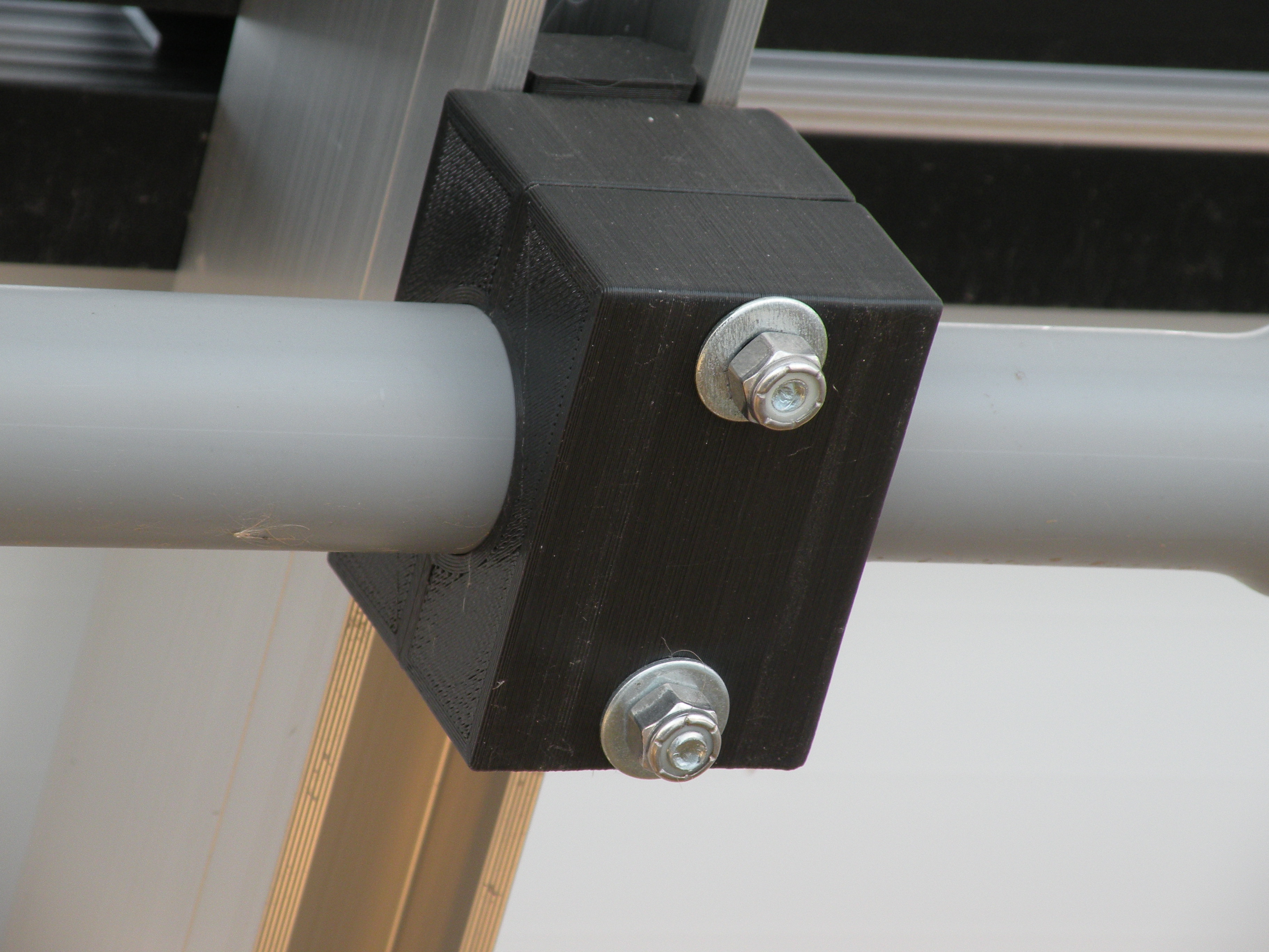
Here we have the conduit clamp assembled with 1/4” bolts held by the SnapNrack mount, which you can see up inside the rail. We used nyloc nuts, but that probably wouldn’t really matter. |

conduit_j_box_lid_01.stl The Junction box is actually a switch, or outlet box. I was not able to find blank covers for them, so I printed covers to fit. |
conduit_wire_plug_01.stl A 3D printed plug that we pushed into the conduit fitting, to protect the wire and keep stuff out of the conduit. |
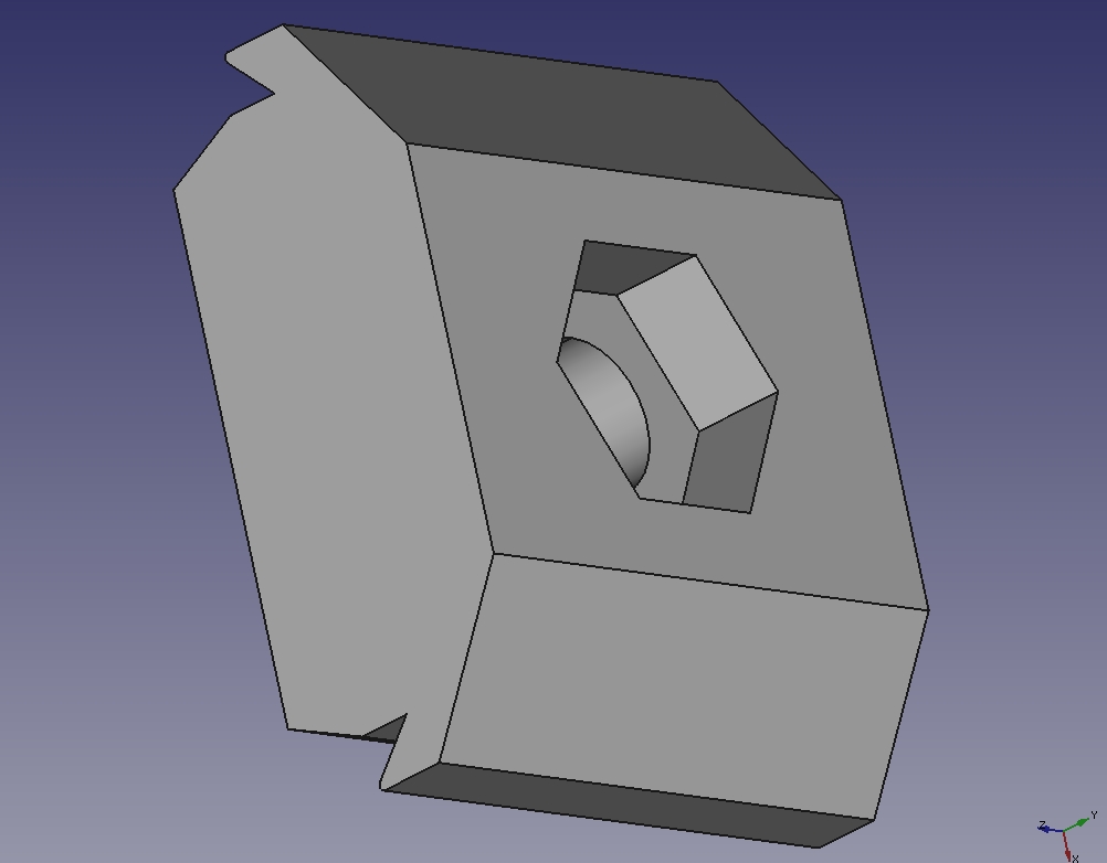
snap-n-rack_mnt_base_01.stl This is the printed snap in anchor that was used for mounting all the Home Run components to the rails. We simply inserted the right length 1/4” bolt so that the head was captured in the hex pocket. |
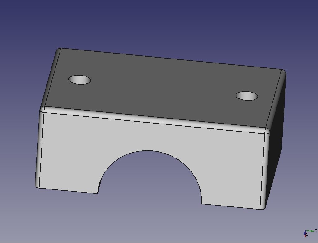
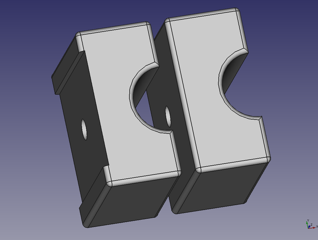
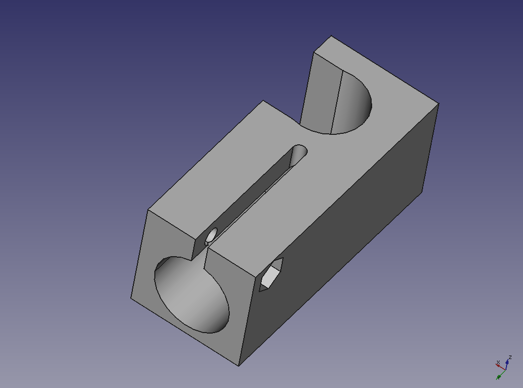
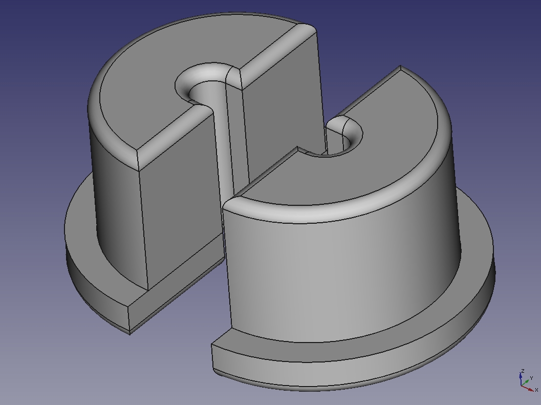
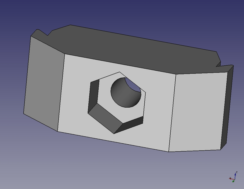
snap-n-rack_conduit_clamp_01.stl |
|
The pictures show the wires all connected because the pictures were taken after everything was up and running.
|
| THINK BEFORE YOU WIRE! |
|
|
|
|
| Connecting the panels into strings |
|
|
|
s-n-r_pvc_mnt_base_02.stl 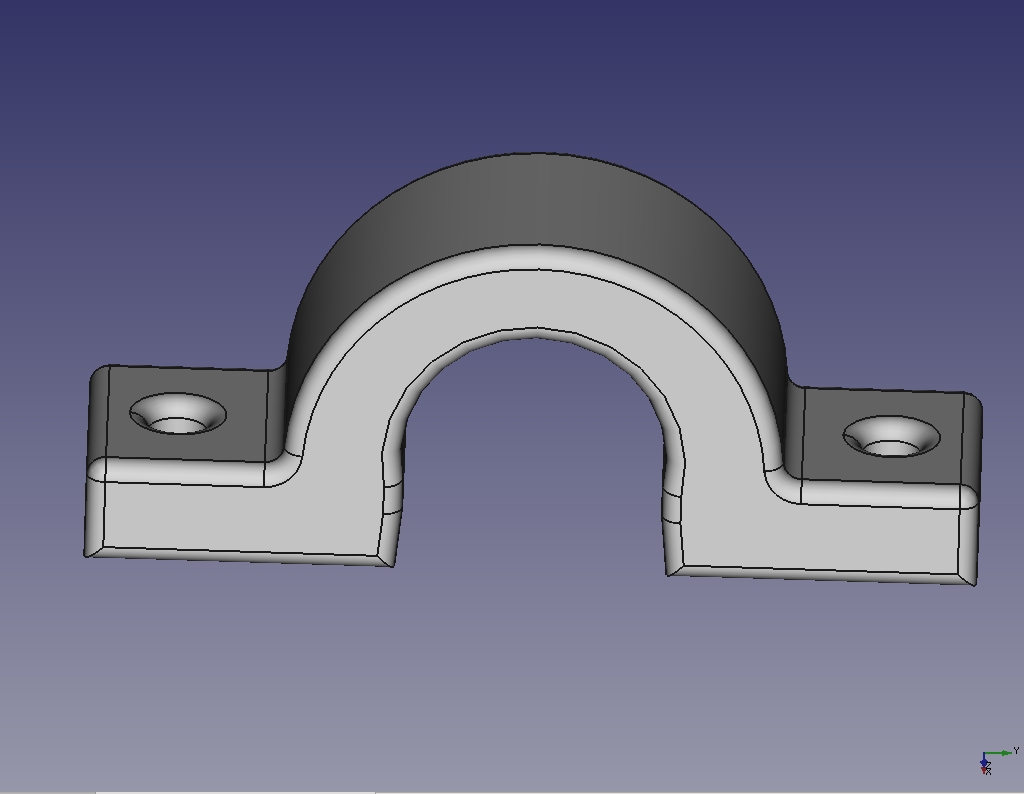
s-n-r_pvc_wire_support_clamp_01.stl |

|
|
Turn on the Sun! Let's generate some power!
NOT QUITE YET, but almost! |
|
|
|
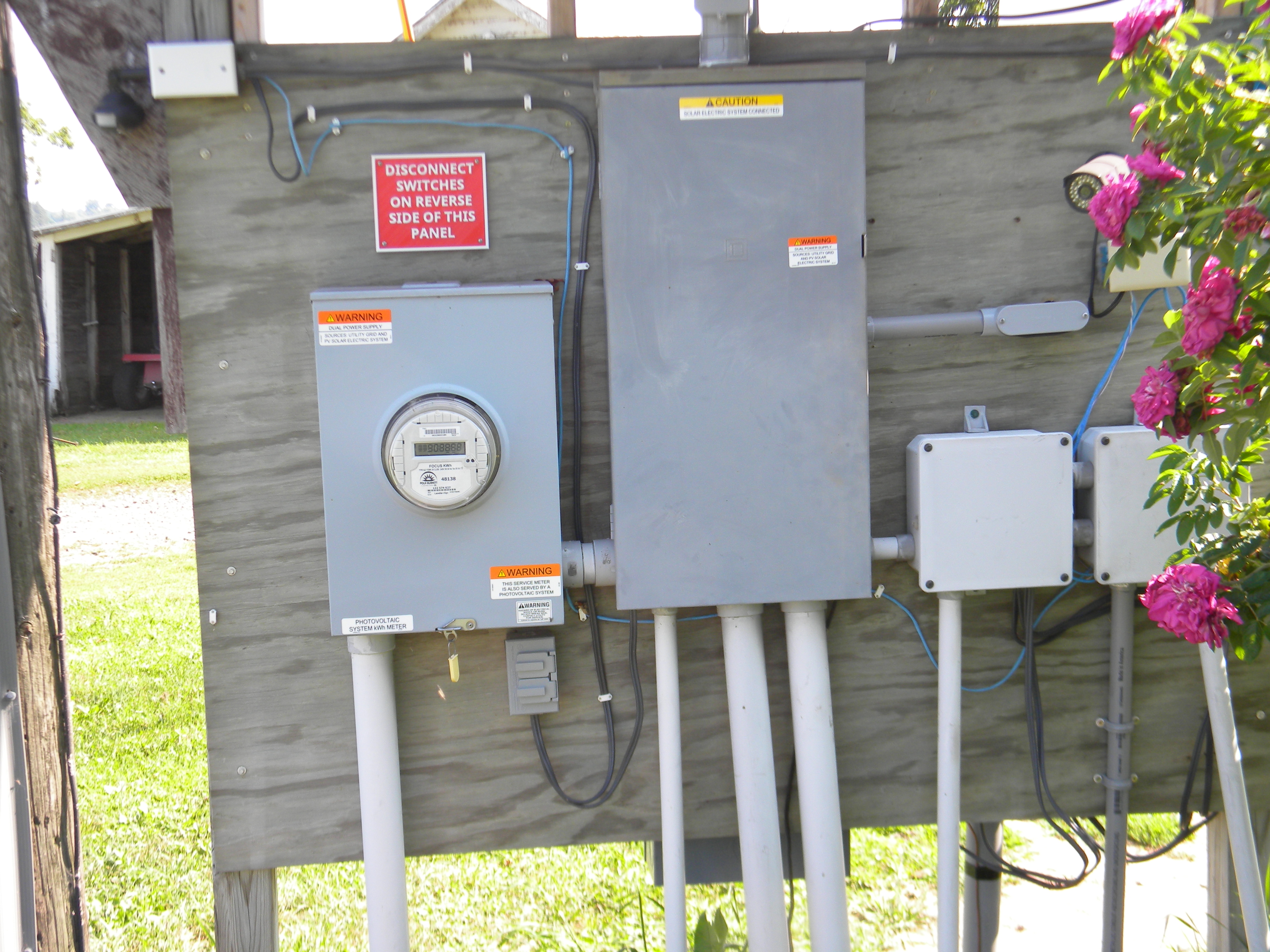
Meter Box and main distribution circuit breaker panel. We 3D printed a custom sign (above the meter box) to inform the power company worker that the main switches are on the back side of this panel. The meter box and the main circuit breaker box have specific NEC stickers on them as well. The breaker box is also labeled inside as to which breaker is being “backfed”. |
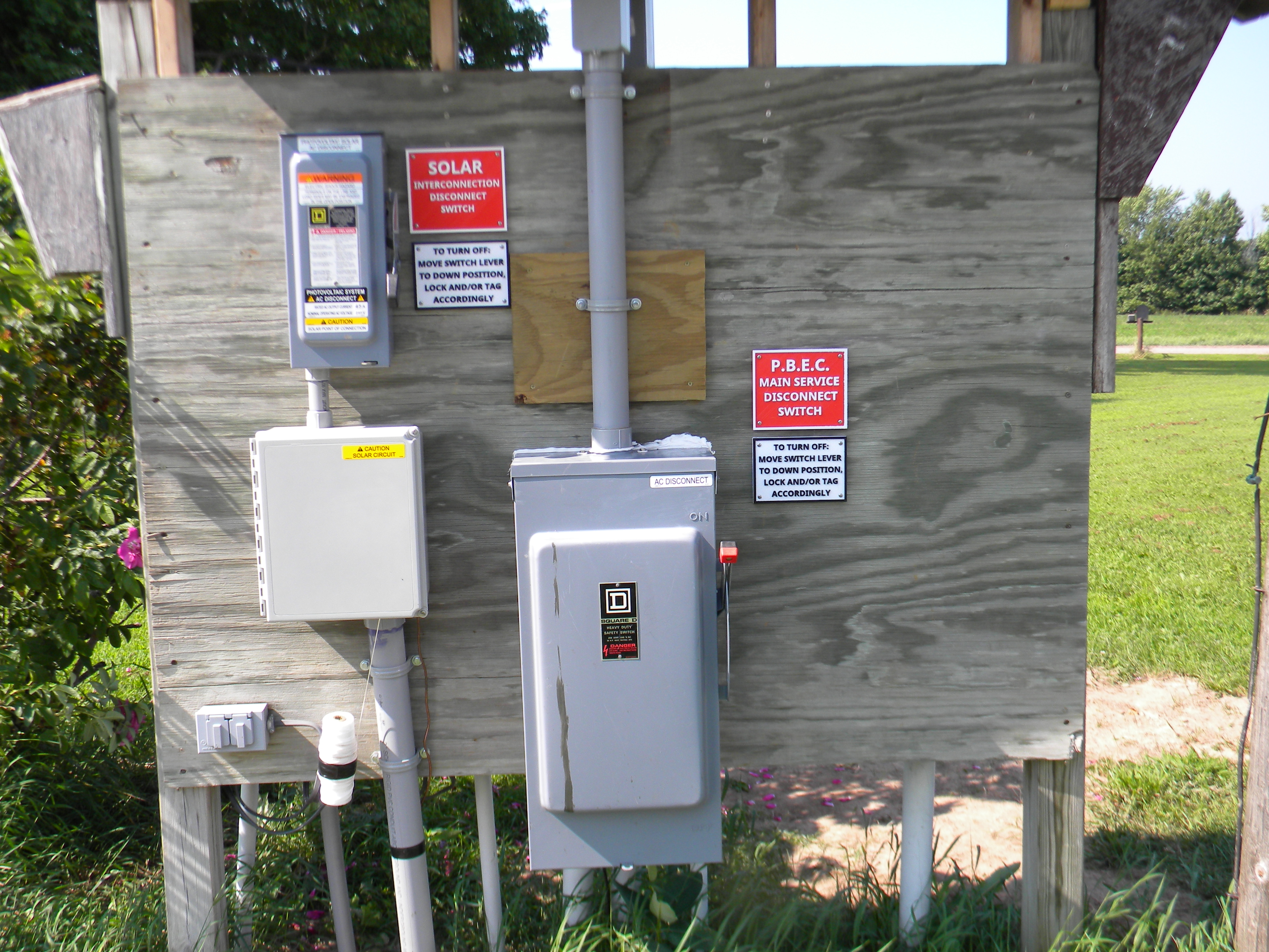
Main Disconnect switches. The upper left switch is clearly defined as where to turn off the solar generator. The lower right switch is more of a “nice to have” than a necessity. I can turn this off if I am working on the system, or during emergencies. Example, when the power is out during a bad storm, when surge potential from lighting is higher. The point here is that anyone who needs to turn if off can quickly see what the switch controls. |
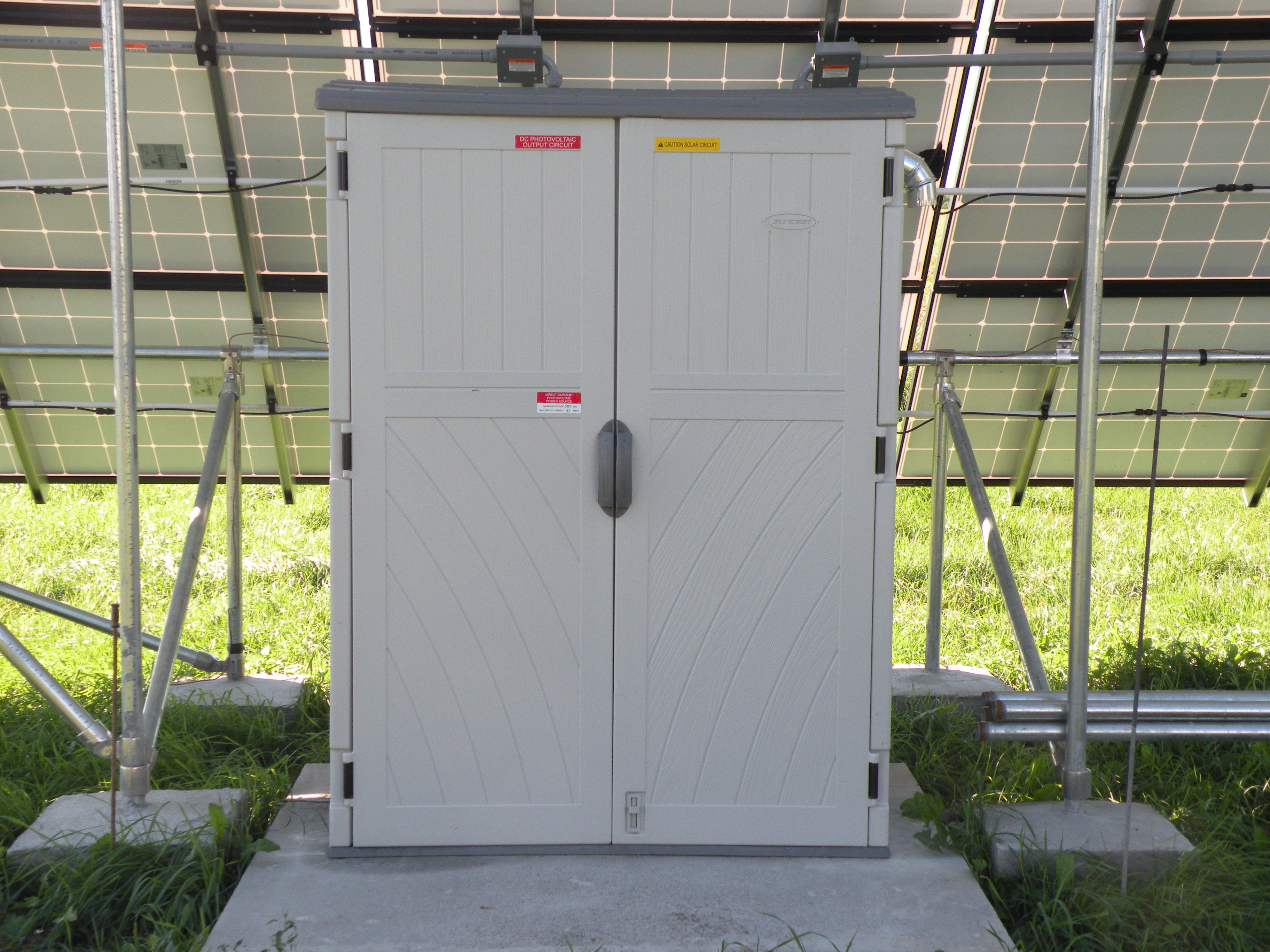
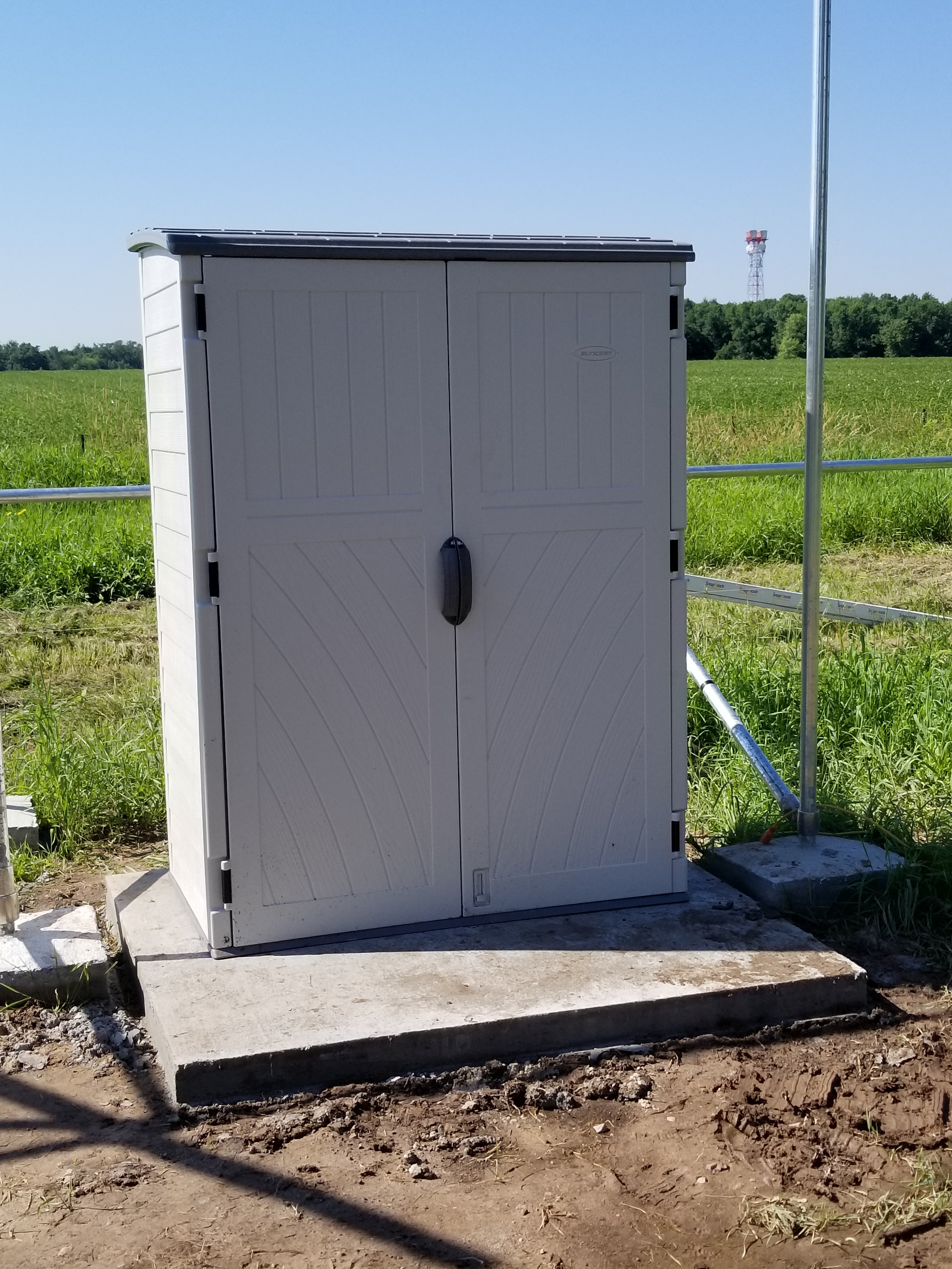
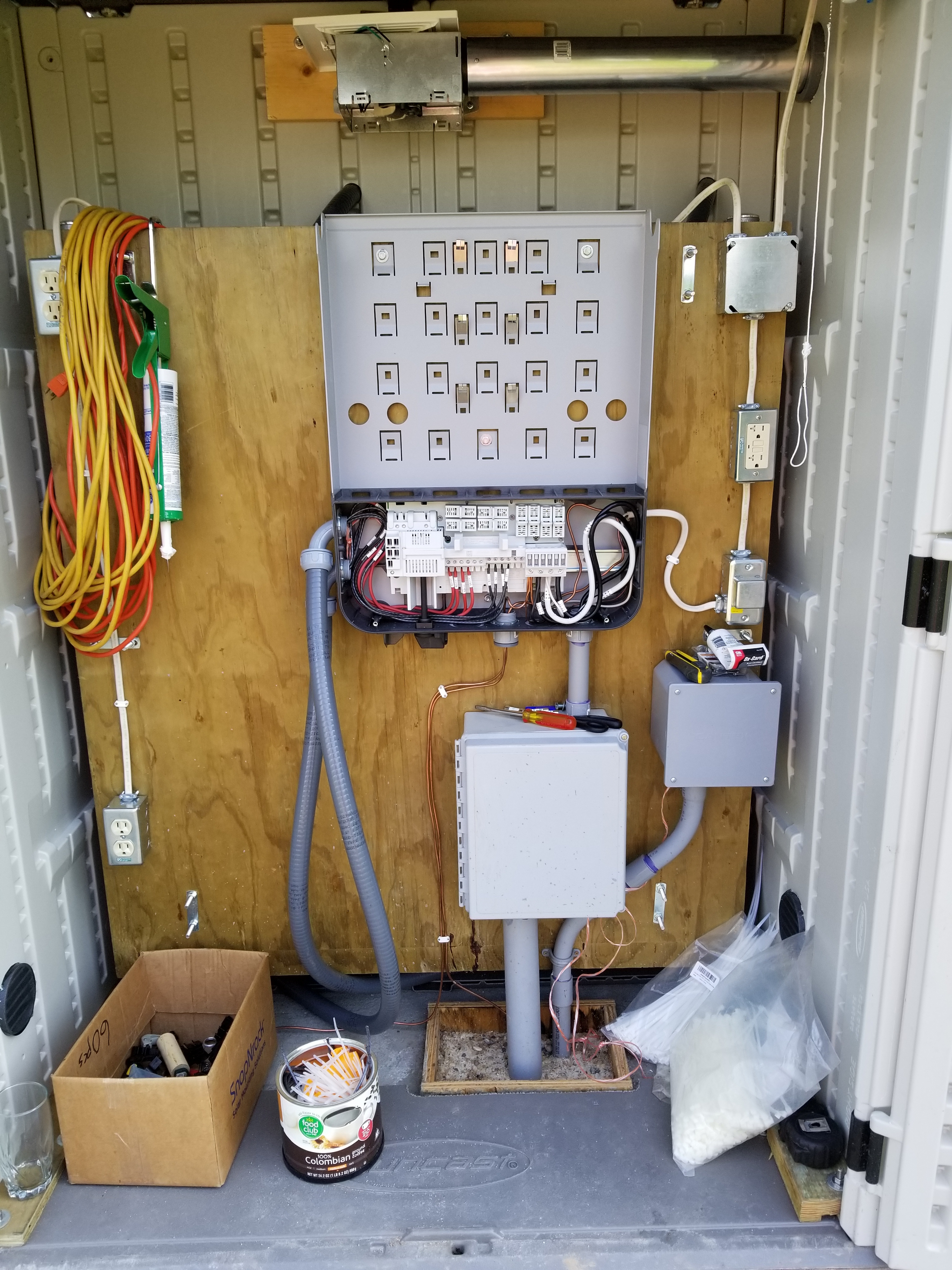
The Fronius Closet. This is where the solar generation begins, and anyone going in there should be aware of the voltage potentials. |
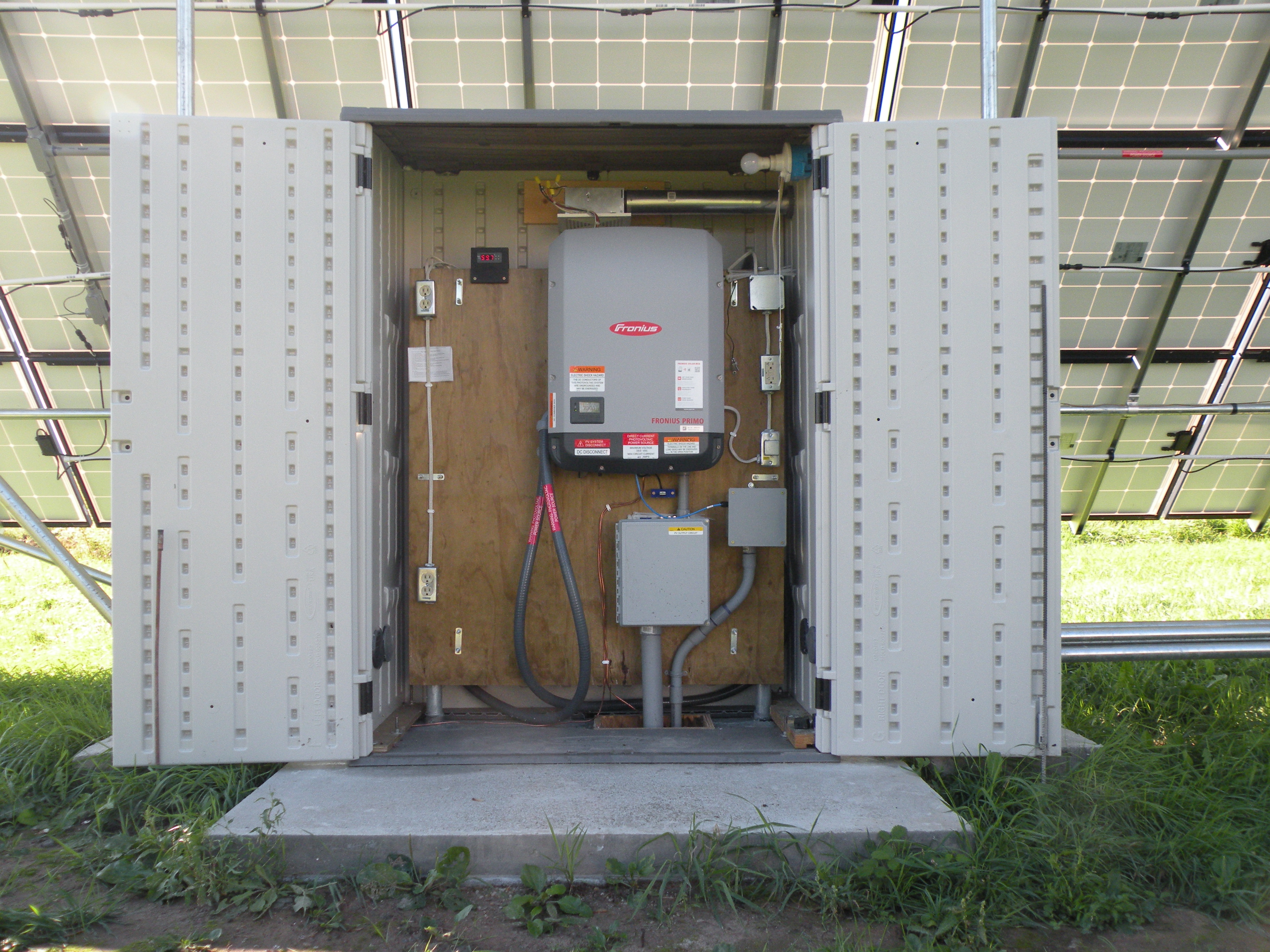
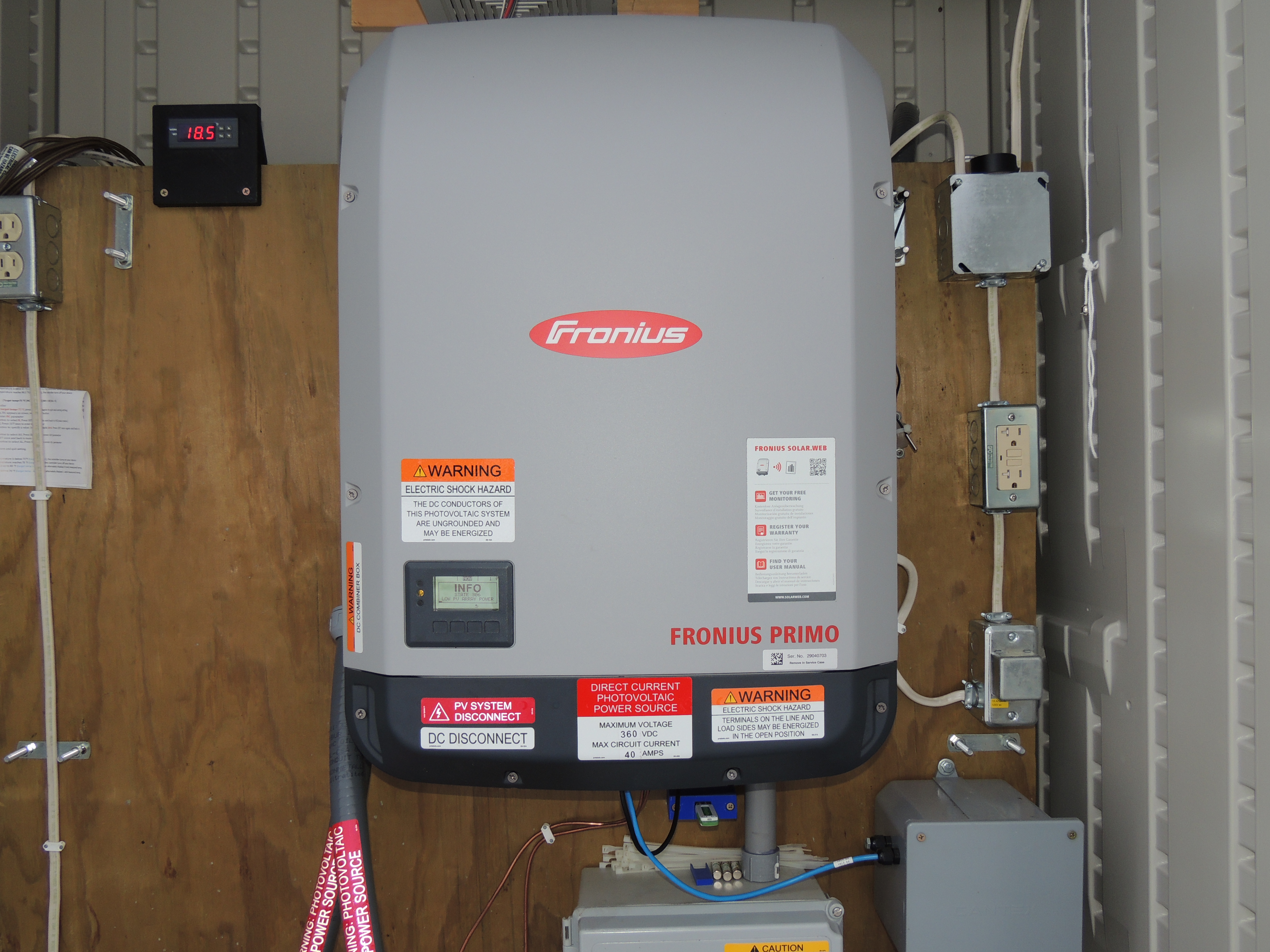
The solar inverter. This also needs to be clearly labeled with what is powering it, and how much power potential that there is. A quick Note: The digital display in the upper left is a temperature controller which controls the bathroom exhaust fan directly above the inverter. We put this in to make sure the Inverter doesn’t overheat on hot summer days when it is outputting close to maximum power. |
Decisions, Opinions, and Stories…
|
|
|
|


Now, take a close look at the picture of the specification label on the back of the solar panels. (click on it to see full size) 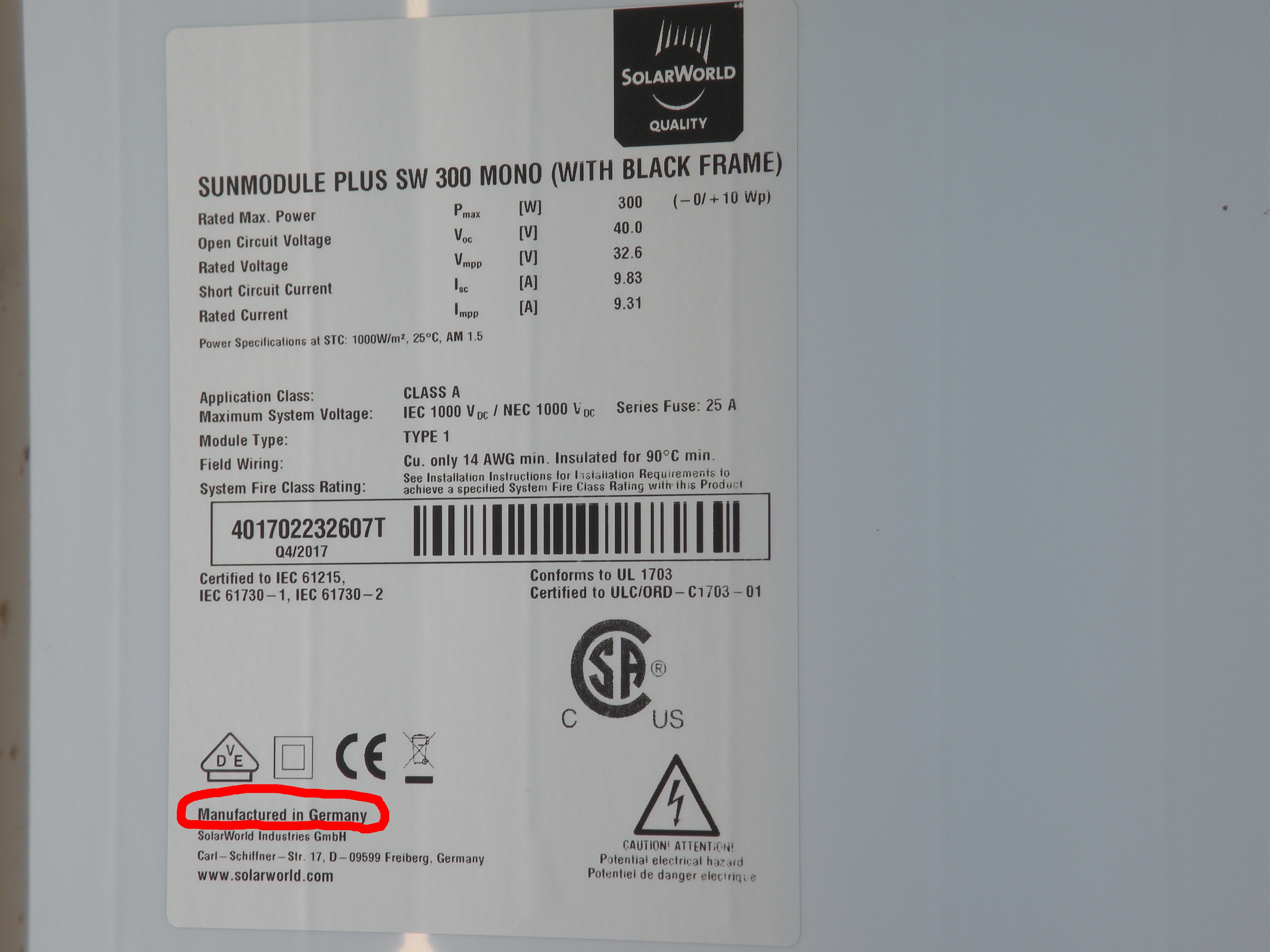
|
|
June 29, 2018
|
This clamp uses the same snap in bolt mount as the Home Run conduit clamps. I cut 12" lengths of pvc pipe, and used the clamp as a drill guide to drill through the pvc.
This clamp uses the same screws, as the pvc clamps that support the panel-to-panel wiring.
|
Grantsburg Parade | Thoreson Park | The Dark Side